Caterpillar and FieldAI are collaborating on physical AI for construction, manufacturing and industrial operations. The deeper idea is bigger than adding autonomy to one machine: FieldAI is building robot-agnostic foundation models designed to operate across different embodiments, while Caterpillar brings heavy-equipment engineering, operational data and large-scale industrial environments. Early applications include autonomous inspection, situational awareness, digital twins and operational optimization using NVIDIA accelerated computing and Omniverse technologies. The important question is whether one risk-aware autonomy stack can transfer across machines, tasks and changing jobsites without requiring every deployment to be engineered from scratch.
Physical AI Gets More Interesting When the Machine Weighs 30 Tons
AI in robotics is easy to demonstrate on a small platform.
A robot dog walks through a room.
A humanoid picks up a box.
A mobile robot follows a route.
Heavy industry is different.
Construction sites change constantly.
Machines operate around people, vehicles, dust, mud, slopes, temporary structures and unfinished terrain.
The cost of a bad decision is much higher.
That is why Caterpillar’s new collaboration with FieldAI is interesting.
The goal is not simply to make one excavator autonomous.
It is to test whether a general-purpose autonomy layer can work across complex industrial environments and multiple types of machines.
Caterpillar Announced the Collaboration on September 2
Caterpillar announced the FieldAI collaboration on September 2, 2026.
The companies say they will work together on physical AI, autonomy, robotics and digital twins.
Caterpillar brings heavy-industry engineering, operational knowledge and data from real jobsites and manufacturing environments.
FieldAI brings robot foundation models and autonomy software designed for unstructured environments.
NVIDIA technologies provide part of the simulation and accelerated-computing layer.
The collaboration is early.
Caterpillar has not announced a specific autonomous excavator, loader or truck product tied to the deal.
The announcement is about a technology direction and development partnership.
FieldAI’s Main Claim Is One Brain Across Many Robots
FieldAI describes its platform as a general-purpose robot brain.
The company’s Field Foundation Models are designed to work across different robot embodiments rather than being built around one fixed machine.
That is a large claim.
Industrial robotics has historically been highly machine-specific.
A system is configured for one arm.
One vehicle.
One sensor arrangement.
One environment.
FieldAI wants to move toward a shared autonomy layer that can transfer more knowledge across platforms.
If that works, adding autonomy to a new machine could become less like writing a new control stack from zero and more like adapting a common intelligence layer.
Robot-Agnostic Does Not Mean Hardware-Agnostic
The phrase robot-agnostic needs a careful interpretation.
A foundation model cannot ignore physics.
An excavator does not move like a quadruped.
A wheeled inspection robot does not have the same sensing or control limits as a haul truck.
Actuators differ.
Mass differs.
Braking distance differs.
Sensor placement differs.
Safety envelopes differ.
The useful meaning of robot-agnostic is that the higher-level autonomy architecture can be reused across embodiments while lower-level interfaces and constraints remain machine-specific.
The model may share reasoning and perception.
The machine still keeps its own physics.
FieldAI Builds Around Uncertainty, Not Perfect Maps
Traditional autonomy often depends on structured assumptions.
Known maps.
Defined lanes.
Preplanned routes.
Controlled environments.
FieldAI positions its system around the opposite problem.
Construction and industrial sites change.
A path that existed yesterday may be blocked today.
Material piles move.
Temporary barriers appear.
People enter the scene.
Lighting changes.
The company says its Field Foundation Models combine data-driven AI with physics-based reasoning and uncertainty awareness.
The goal is to let robots operate when the world cannot be perfectly preprogrammed.
A Belief World Model Is the Core of FieldAI’s Current Architecture
FieldAI describes its EDGE platform around a Belief World Model.
The concept is that the robot maintains an internal representation of what it thinks is happening in the environment and how uncertain those beliefs are.
That matters because robots never observe the physical world perfectly.
A camera can be blocked.
LiDAR can have incomplete coverage.
A moving object may disappear behind equipment.
The system has to reason about partial information.
Risk-aware autonomy is less about pretending uncertainty does not exist and more about making uncertainty part of the decision process.
Heavy Equipment Makes Risk Awareness Essential
A lightweight indoor robot can often stop quickly.
Heavy equipment cannot.
Momentum matters.
Blind spots matter.
Terrain matters.
A machine may need several meters to stop safely.
That means perception confidence cannot be treated as an abstract model score.
Uncertainty has physical consequences.
If the autonomy stack is unsure whether an area is clear, the safest action may be to slow down, stop or request human input.
That is why risk-aware modeling is more meaningful in heavy industry than a generic claim that a model can “see” the environment.
The First Applications Are Not Full Autonomous Earthmoving
Caterpillar lists four early application areas.
Autonomous inspection.
Digital twins.
Situational awareness.
Operational optimization.
That list is revealing.
The first value does not require a machine to perform every construction task without a human.
Inspection alone can be valuable.
A robot can repeatedly capture site conditions.
A digital twin can update from those observations.
AI can identify changes or risks.
Simulation can test better workflows.
This is a more practical path than jumping directly to full autonomy.
Autonomous Inspection Is the Lowest-Risk Entry Point
Inspection is one of the strongest early use cases for physical AI.
A robot can travel through a site and collect visual, depth and other sensor data.
It can revisit the same areas repeatedly.
Humans do not have to enter every difficult or hazardous location.
The task is valuable even if the robot never moves a bucket of dirt.
That creates an adoption path.
First, the system observes.
Then it builds trust.
Then autonomy can expand into more consequential actions.
Every Inspection Run Can Also Build a Digital Twin
FieldAI’s collaboration with NVIDIA shows how inspection becomes more than inspection.
The company says robots collect multimodal data during normal missions.
Vision.
Depth.
LiDAR.
Other sensors.
That data can be transformed into high-fidelity digital reconstructions using NVIDIA Omniverse technologies.
The result is a digital twin that can evolve as the physical site changes.
A robot performing ordinary work becomes a mobile reality-capture system.
A Living Digital Twin Is More Useful Than a One-Time Scan
Traditional digital twins can become stale.
A construction site changes every day.
A factory layout changes.
Equipment moves.
Temporary structures appear.
If the digital model takes weeks or months to rebuild, it may describe a site that no longer exists.
FieldAI argues that robots can update the model continuously as a byproduct of operations.
That turns the digital twin from a project deliverable into an ongoing data layer.
The Real-to-Sim Loop Is the More Important NVIDIA Connection
NVIDIA Omniverse is not only being used to make attractive 3D models.
FieldAI describes a real-to-sim pipeline.
Robots operate in the physical world.
Their sensors capture the site.
Omniverse reconstruction tools turn that data into simulation-ready environments.
Those environments can then be loaded into Isaac Sim and Isaac Lab.
Autonomy can be tested against a reconstruction of the real site.
The results can feed back into future deployments.
Real operations create simulation.
Simulation improves the robot.
The robot returns to the real world.
That Loop Creates a Data Flywheel
Every deployment can create more training and validation data.
Every site adds different terrain.
Different obstacles.
Different lighting.
Different machine layouts.
Different failure cases.
If that data enters a common model-development pipeline, the autonomy system can improve across deployments.
FieldAI calls this a data flywheel.
The strategic advantage is obvious.
The more industrial environments the system sees, the harder it becomes for a new competitor to reproduce the same diversity of real-world experience.
Caterpillar Brings a Different Kind of Scale
FieldAI already deploys robotics systems across industrial environments.
Caterpillar brings another scale entirely.
Construction equipment.
Mining equipment.
Factories.
Dealer networks.
Long-lived machines.
Operational data accumulated across decades.
A partnership with a major equipment manufacturer gives an autonomy company access to use cases that are difficult to reproduce in a robotics lab.
The challenge is also larger.
A technology that works on one inspection robot is not automatically ready for a fleet of heavy machines.
Caterpillar Already Has Its Own Autonomy History
Caterpillar is not entering autonomy for the first time.
The company has long deployed autonomous mining systems and machine-control technologies.
That existing background matters.
FieldAI is not replacing an empty stack.
The collaboration adds a newer foundation-model approach to an organization that already understands industrial automation, safety engineering and large-scale equipment operations.
The interesting question is whether general-purpose models can expand autonomy beyond tightly engineered environments.
Mining Autonomy Is Easier Than a Chaotic Construction Site in One Important Way
Large mining operations can be highly structured.
Routes can be mapped.
Traffic rules can be controlled.
Access can be restricted.
Machines can operate in managed areas.
Construction sites are often less predictable.
People move through the environment.
Layouts change quickly.
Temporary materials appear.
Multiple contractors work simultaneously.
That makes general autonomy harder.
FieldAI’s value proposition is specifically aimed at those environments where traditional automation becomes expensive to configure or brittle when conditions change.
Traditional Automation Is Strongest When the World Stays the Same
Automation works beautifully in repeatable environments.
A factory robot can perform the same motion thousands of times.
A conveyor follows a fixed path.
A machine-vision camera inspects the same product.
The system becomes harder to scale when the world changes faster than engineers can reconfigure it.
Foundation-model robotics is trying to reduce that reconfiguration burden.
Instead of encoding every situation manually, the autonomy system learns broader patterns and adapts.
That promise is powerful.
It is also much harder to validate.
Generalization Is the Whole Bet
The economic argument for general-purpose autonomy depends on reuse.
If every new site requires months of custom engineering, deployment does not scale well.
If one model can transfer useful behavior from one environment to another, integration cost can fall.
The model does not have to work perfectly with zero adaptation.
It only has to reduce the amount of machine-specific and site-specific engineering enough to change the economics.
That is what Caterpillar and FieldAI are really testing.
Digital Twins Can Make Validation More Site-Specific
A general model creates a safety problem.
How do you know it will behave correctly at this particular site?
Digital twins provide one answer.
Capture the real environment.
Reconstruct it.
Run simulated missions.
Introduce edge cases.
Test routes.
Change layouts.
Evaluate policies before the robot operates physically.
The simulation does not replace real validation.
It gives engineers another layer where failures can be found before they happen around real equipment.
Simulation Is Only Useful If It Represents the Hard Parts
A clean synthetic environment is easy to simulate.
Real sites are messy.
Dust.
Debris.
Uneven terrain.
Partial visibility.
Temporary structures.
Dynamic obstacles.
FieldAI’s approach is interesting because the simulation environment begins with data captured from actual deployments.
That can preserve site-specific complexity that a manually built digital twin might miss.
The closer the simulation is to the operating environment, the more useful it becomes for regression testing and scenario analysis.
NVIDIA Supplies the Infrastructure, Not the Robot Intelligence
The partnership includes NVIDIA accelerated computing and Omniverse technologies.
The roles should stay clear.
FieldAI provides the autonomy models and robot-intelligence layer.
Caterpillar provides industrial machines, engineering and operational expertise.
NVIDIA provides simulation, reconstruction and computing infrastructure used in the development pipeline.
That three-layer structure matters because physical AI increasingly depends on an ecosystem rather than one company building everything.
Operational Optimization May Be Valuable Before Full Autonomy
Caterpillar also lists operational optimization as an early use case.
A digital twin can show how machines, people and materials move through a site.
Simulation can test alternative layouts.
AI can identify bottlenecks.
Maintenance data can be connected to site conditions.
A company may gain meaningful productivity improvements without removing human operators.
That makes physical AI easier to deploy incrementally.
Observation and optimization first.
More autonomous execution later.
Situational Awareness Is Another Intermediate Layer
Situational awareness sits between sensing and control.
A robot or machine can identify what is happening around it and surface useful information to people.
Potential hazards.
Blocked routes.
Changing site conditions.
Equipment positions.
Areas that need inspection.
The system does not need authority to perform every action.
It can make the environment more legible to operators and supervisors.
That can improve decision-making while keeping humans inside the control loop.
The Human-Machine Boundary Is Part of Caterpillar’s Message
Caterpillar frames the collaboration around combining human expertise with AI-powered machines.
That language matters.
Heavy industry will not switch from human-operated equipment to fully autonomous fleets overnight.
Mixed environments are more likely.
Some machines autonomous.
Some remote-controlled.
Some human-operated.
Robots performing inspections.
AI systems providing recommendations.
Humans handling exceptions and high-consequence decisions.
The hard problem is not only autonomous capability.
It is coordination across all of those modes.
A Universal Robot Brain Still Needs Machine-Specific Safety Layers
Even if FieldAI’s model generalizes across platforms, safety cannot be universal in the same way.
A large articulated truck has different stopping behavior from a small quadruped.
An excavator has a rotating upper structure and a large working envelope.
A robotic arm has joint limits and collision zones.
Each machine needs hard constraints close to the control layer.
The foundation model can choose a goal.
The equipment still needs deterministic limits on what is physically allowed.
This Is Where Physical AI Differs From Software Agents
A software agent can make a mistake and often retry.
A physical machine may not get a second chance.
A collision cannot be undone.
A slope failure cannot be rolled back.
A person entering a machine path changes the risk instantly.
That makes uncertainty calibration, fail-safe behavior and verification central to industrial autonomy.
The model cannot simply be impressive.
The complete system has to be predictable enough to earn operational trust.
FieldAI Says It Already Operates Across Hundreds of Sites
FieldAI says its technology has been tested and deployed across hundreds of complex industrial environments.
The company also says its deployments span multiple continents and several robot types.
Those are company-reported deployment claims.
They are useful because they show the technology is beyond a single laboratory demo.
They should not be converted into an independent measure of reliability.
Scale of deployment is not the same thing as verified safety performance.
The Company Has Raised More Than $400 Million
FieldAI announced in 2025 that it had raised $405 million across two funding rounds.
Its investor list includes major venture and strategic investors.
That capital gives the company resources to build expensive robotics infrastructure, collect field data and support deployments.
Physical AI is capital intensive.
Models need data.
Robots need hardware.
Sites need integration.
Safety testing takes time.
A large funding base matters because the product has to survive the gap between a research result and an industrial platform.
The Caterpillar Partnership Is More Important Than a Humanoid Demo
Robotics headlines often focus on humanoids because they are visually striking.
Caterpillar’s partnership points toward a different future.
The most valuable robot may be the machine already designed for the job.
An excavator already has the right body for digging.
A haul truck already has the right body for moving material.
A quadruped may be better for inspection.
The autonomy layer does not need every robot to look human.
It needs to understand enough different embodiments to use the right machine for each task.
Embodiment-Agnostic AI Could Reduce the Pressure to Build One Universal Robot
The idea of one humanoid doing everything is attractive because it simplifies the hardware story.
One body.
Many tasks.
FieldAI is pursuing another kind of universality.
Many bodies.
One higher-level intelligence architecture.
That may fit industrial reality better.
Factories and jobsites already contain specialized machines.
Replacing all of them with humanoids would be expensive and often unnecessary.
Adding a reusable autonomy layer to existing machine categories could be a faster route to general-purpose physical AI.
The Real Product May Become the Autonomy Layer
If robot intelligence becomes portable, the strategic value shifts.
The robot body becomes one part of the system.
The autonomy layer carries perception, world modeling, planning, risk reasoning and learned experience.
That starts to resemble what operating systems did for computers.
Different hardware.
A common software layer.
Robotics is not there yet.
But Caterpillar working with a company that explicitly describes itself as one brain for many robots shows where the industry wants to go.
What Caterpillar and FieldAI Have Actually Confirmed
Caterpillar and FieldAI announced a collaboration on September 2, 2026.
The companies say they will work on physical AI, robotics, autonomy and digital twins for complex jobsites and manufacturing environments.
Caterpillar lists autonomous inspections, site and facility digital twins, enhanced situational awareness and operational optimization as early application areas.
The collaboration combines Caterpillar’s industry expertise and operational data with FieldAI’s robot-agnostic foundation models.
The companies also say NVIDIA accelerated computing and Omniverse technologies will support the work.
FieldAI describes its models as combining data-driven AI, physics-based reasoning and uncertainty awareness.
No specific fully autonomous Caterpillar production machine was announced as part of the release.
What We Should Not Claim
We should not say Caterpillar has launched a fully autonomous excavator powered by FieldAI.
It has not announced that.
We should not say one FieldAI model already controls every Caterpillar machine.
The collaboration is broader and earlier than that.
We should not treat robot-agnostic as meaning the physical differences between machines disappear.
We should not claim the system eliminates human operators.
Caterpillar explicitly frames the work around human expertise and AI-powered machines.
We should not turn FieldAI’s deployment scale into an independent reliability statistic.
And we should not claim digital twins prove real-world safety.
Simulation is one validation layer, not a substitute for physical testing.
The Bigger Shift Is From Autonomous Machines to Portable Autonomy
The first generation of industrial autonomy was machine-specific.
One autonomous haul truck.
One warehouse robot.
One programmed arm.
Caterpillar and FieldAI are testing a more ambitious idea.
Build an autonomy layer that can move between machines, learn from many sites and use the physical world itself to improve simulation and validation.
If that works, the important product is no longer one autonomous machine.
It is portable autonomy.
A common intelligence layer that can understand enough about different machines to make more of the industrial world programmable.
That is a much bigger shift than putting AI inside an excavator.
Anthropic’s Model Hardware Standard is an early attempt to give AI agents a common way to discover, understand and operate programmable physical devices. Instead of writing a bespoke integration for every microscope, liquid handler, robot arm or laser controller, MHS introduces standardized drivers, simple read/write primitives, machine-readable device descriptions and device-level safety limits. Early pilots show why this matters: agents have coordinated multiple lab instruments, adapted microscopy settings in real time and helped develop a quantum-laser recovery controller that later succeeded in 695 of 700 blind trials. The important caveat is equally physical: current models still misunderstand real-world failures, so MHS is being tested as a research preview with expert oversight before Anthropic plans to open-source it.
AI Agents Have Learned to Use Software Tools — Physical Machines Are the Next Problem
AI agents are already becoming comfortable inside software.
They can open files.
Run commands.
Use APIs.
Call databases.
Control browsers.
Chain multiple tools together.
Physical equipment is much harder.
A microscope may use one vendor API.
A robotic arm may use another SDK.
A camera may expose a different interface.
A laser controller may need custom scripts written by someone who understands the hardware.
Even when every machine is technically programmable, connecting them into one reliable workflow can take weeks or months.
Anthropic’s Model Hardware Standard, or MHS, is an attempt to make that layer look more uniform to AI agents.
MHS Is Not a Robot Model
MHS is not a new Claude model.
It is not a robot operating system.
It is not a general-purpose replacement for every industrial control protocol.
Anthropic describes it as a shared specification for AI agents to operate physical devices safely.
The current version is a limited research preview being tested with scientific labs, robotics companies, electronics firms and manufacturers.
The standard is designed to work with devices that already expose a programmable interface.
It is also model-agnostic.
Anthropic says any agent harness can access MHS using standard mechanisms, including Model Context Protocol.
That separation is important.
The intelligence layer and the hardware interface are not supposed to be the same thing.
The Basic Problem Is That Every Machine Speaks Its Own Language
A research lab rarely buys every instrument from one vendor.
One camera comes with Python bindings.
A detector may use MATLAB.
Another controller may be wrapped in C#.
A microscope may require a proprietary application.
A robotic arm may expose its own SDK.
Scientists then build glue code between all of them.
The result can work.
It is also fragile.
The integration knowledge often lives in scripts, local documentation or in the memory of the person who built the rig.
MHS tries to move that knowledge into a common hardware-facing layer.
The Core of MHS Is a Standardized Driver
Anthropic describes the MHS driver as the translation layer between a computer and a hardware device.
Instead of forcing the agent to understand every vendor-specific interface directly, the driver presents a simpler set of standardized operations.
Anthropic gives basic examples such as read and write.
Read might mean get the temperature.
Write might mean set the temperature.
Real devices obviously expose richer behavior than two verbs.
The point is the abstraction.
The agent works through a predictable interface even when the underlying hardware is different.
Discovery Matters as Much as Control
Controlling a device is only useful if the agent knows the device exists.
MHS makes connected hardware discoverable in a standard format.
That means an agent can find available equipment across a network instead of depending on a custom integration written specifically for one workflow.
This sounds similar to software tool discovery.
The difference is consequence.
A mistaken software tool call may produce a bad file.
A mistaken physical call can move a robot, damage a sample or push an optical system outside a safe operating range.
Discovery therefore has to carry more than a function name.
MHS Tries to Give the Agent Physical Context the Code Does Not Contain
A hardware API can tell software which function moves a robotic arm.
It may not tell the model how heavy the arm is.
How far it can safely travel.
Which movement risks a collision.
Which setting can damage a sample.
Anthropic says MHS drivers can include natural-language tags describing machine characteristics that are difficult to infer from code alone.
The user can enter this information directly or let an agent interview them about the hardware setup.
The driver then produces a reference description of what the machine can measure, what can be adjusted and which safety limits should be enforced.
This converts some physical knowledge from tacit expertise into explicit machine context.
The Safety Boundary Is Supposed to Live at the Device Layer Too
One of the stronger design choices is that safety is not left entirely to the language model.
MHS can enforce device-level limits.
In a microscopy example at HHMI Janelia, the researcher describes using those limits to prevent the agent from applying excessive laser power that could bleach fluorescent molecules and degrade the sample.
That is the correct direction for physical AI.
Do not ask a probabilistic model to remember every safety rule on every turn.
Put critical limits closer to the machine.
The model can decide what it wants to do.
The hardware interface still decides what it is allowed to do.
MCP Is One Control Path — Not the Whole Standard
It would be easy to describe MHS as MCP for robots.
That is too simple.
Anthropic says MHS can expose hardware control through three mechanisms: MCP, a command-line interface and code files through APIs.
Those paths serve different timing requirements.
An agent can reason interactively through MCP.
It can invoke commands through a CLI.
For long-running or faster operations, it can package sequences into code so the device can execute without waiting for the model to reason at every step.
That last part is especially important for real machines.
Physical control loops often cannot pause while an LLM thinks.
The Interesting Pattern Is Agent Exploration Followed by Deterministic Code
Anthropic describes an MHS experiment in which Claude adjusted a laser, observed the result through a camera and repeated the process while learning how the beam responded.
Then the agent packaged what it learned into code.
The final alignment procedure could run as a deterministic script with one command.
That pattern may be more useful than keeping the agent permanently in the lowest-level control loop.
Let the model explore.
Let it search.
Let it infer a better procedure.
Then compile the useful behavior into inspectable deterministic software.
The agent becomes a system designer rather than a permanent joystick.
This Is a Different Vision of Physical AI
The popular image of physical AI is a humanoid robot controlled continuously by a large model.
MHS points toward another architecture.
The AI does not have to directly generate every motor command.
It can operate at a higher level.
Read state.
Select a procedure.
Adjust parameters.
Call a deterministic routine.
Observe the result.
Escalate when something unexpected happens.
This hierarchy is closer to how complex automation already works.
The model adds flexible reasoning around the deterministic machinery instead of replacing every controller with a chatbot.
A University of Washington Demo Connected a Robot Arm and a Liquid Handler
One research-preview example came from the University of Washington Baker and Pinglay labs.
The team connected a liquid handler and an open-source robotic arm through MHS.
The liquid handler dispensed reagents into a plate.
The robotic arm waited until that step finished.
Then it removed the completed plate and loaded the next one.
Claude Code coordinated the sequence.
According to the researchers, repeated tests completed without the two instruments colliding.
The agent observed completion signals before triggering the next device.
The important result is not that an arm moved a plate.
Industrial automation has done that for decades.
The interesting part is that two heterogeneous devices were orchestrated through one agent-facing layer.
The Same Lab Connected Six Instruments in Under a Week
The University of Washington researcher says connecting six instruments through MHS took less than a week, including time spent writing drivers.
That is not a universal benchmark.
It is one early case.
But it illustrates the problem MHS is trying to solve.
The same researcher describes previous automation attempts involving weeks of evaluating platforms, chasing vendor support and building glue code.
If standardized drivers can be reused across labs, integration work can compound.
One team writes a robust driver.
Another team uses it instead of starting from zero.
That is how a hardware standard can become more valuable than a one-off automation demo.
Genentech Used MHS to Coordinate Three Pieces of Lab Equipment
Genentech tested MHS on a proof-of-concept laboratory workflow involving a liquid handler, robotic arm and microplate reader.
Claude acted as the orchestration layer across the three devices.
Anthropic’s page says the time from non-automated equipment readiness to a completed dilution curve, including an autonomous rerun, was eight hours.
The comparison given by the participating team is that a vendor-delivered automated setup would typically take multiple weeks.
This is a partner-reported result from an early proof of concept.
It should not be read as a guarantee that MHS compresses every lab-integration project to eight hours.
The Failure Case Is More Important Than the Successful Demo
The Genentech pilot also exposed a weakness.
Claude encountered runtime errors caused by bubbles forming during mixing.
Its initial response was software-like.
Retry the operation.
Change parameters.
Try again.
But the physical system behaved differently.
Retrying agitated the liquid further and created more bubbles.
The researchers had to guide Claude toward a gentler physical correction.
Anthropic highlights this example itself.
That is important.
A model trained through text and images can understand an API while still misunderstanding what matter, friction, fluid and force are doing in the real world.
A Hardware Error Is Not Always a Software Error
Software agents are trained by an environment where many failures can be solved with another command.
Retry the request.
Restart the service.
Change the parameter.
Re-run the test.
Physical systems do not always forgive that strategy.
A liquid can foam.
A sample can degrade.
A motor can collide.
A laser can damage material.
A machine can overheat.
The difference is irreversibility.
An agent operating real hardware needs a richer model of cause and effect than an agent fixing a compiler error.
MHS standardizes access.
It does not automatically give the model physical intuition.
HHMI Janelia Shows Why One Shared State Can Change a Microscope Rig
MHS began partly from a real integration problem at HHMI Janelia Research Campus.
One researcher was working with a brain-imaging rig made from lasers, motorized focusers, specialized cameras and other devices from different vendors.
The early idea was to place the rig’s state in a standardized shared-memory dictionary.
That evolved into MHS.
Another Janelia project describes a microscopy setup previously spread across seven vendor programs.
With the rig exposed through a common state layer, an agent can make higher-level decisions without separately learning seven different control systems.
Agentic Microscopy Is About Choosing What to Observe Next
Microscopy makes the value of adaptive agents easier to see.
Traditional experiments often start with fixed parameters.
Image this region.
At this speed.
At this resolution.
For this long.
But biological systems change while the experiment is running.
A fixed setting may miss the interesting event.
In the Janelia work, the agent can enter at decision points and choose acquisition parameters based on what the system is observing.
That is more than automating a button press.
The experiment becomes closed-loop.
Observe.
Analyze.
Decide what to measure next.
Then change the acquisition plan.
MHS Does Not Remove the Physics
A standard interface cannot repeal physical trade-offs.
Imaging faster can reduce coverage.
More light can damage a sample.
Higher precision can cost time.
A robot can only move within its mechanical limits.
The Janelia researchers explicitly note that MHS does not remove these trade-offs.
What it changes is how quickly an experiment can move through the parameter space.
That is the right way to describe the value.
MHS does not make hardware infinitely capable.
It makes hardware easier for agents and humans to coordinate.
The QuEra Pilot Is the Strongest Demonstration
The most striking MHS example comes from QuEra Computing.
QuEra builds neutral-atom quantum computers.
The machines depend on extremely precise lasers.
If a laser loses its frequency lock, quantum operations can begin to fail.
A human expert may need five to ten minutes to restore the lock.
QuEra had already spent months building a bespoke automated recovery script.
That script worked about 58% of the time and took roughly 150 seconds per attempt.
Then the team gave Claude controlled access to the laser system through MHS.
Claude Did Not Simply Operate the Laser — It Redesigned the Recovery Procedure
QuEra used multiple Claude instances in an iterative loop.
One proposed a hypothesis.
Another modified the recovery script.
Another ran the updated script against the live laser and logged the result.
Another reviewed the logs and decided what to try next.
The cycle repeated hundreds of times overnight.
By morning, Anthropic reports that recovery took around six seconds and succeeded 96% of the time in the development run.
The important point is that the model was not only executing a fixed procedure.
It was searching for a better one.
The Blind Test Reached 695 Successful Recoveries Out of 700
After the development loop, QuEra tested the finished script against randomized induced disturbances with no agent controlling the test.
Across 700 trials, the controller recovered the correct lock 695 times.
That is the reported 99.3% success rate.
The hardest disturbances took roughly 10 to 14 seconds.
Simpler ones took less.
Again, the result needs precise wording.
This is a QuEra and Anthropic pilot on one laser system.
It is not evidence that MHS makes arbitrary hardware 99.3% reliable.
But it is strong evidence for a particular workflow: use the agent to discover a better control strategy, then deploy the resulting deterministic procedure.
The Production Artifact Was Inspectable Code, Not an Autonomous Agent
The most reassuring detail is what QuEra ended up with.
The relock controller became a deterministic, inspectable script that could run without an AI agent controlling it.
That matters for engineering.
Critical systems often need repeatability.
A deterministic controller can be reviewed.
Versioned.
Tested.
Rolled back.
The agent can still be useful during development and optimization.
But the final artifact can be ordinary software.
That architecture may be one of the most practical ways to bring frontier models into physical systems without handing them permanent unrestricted control.
Some Tasks Still Keep the Agent in the Loop
Not every task can be compiled into one fixed script.
QuEra also used Claude to tune interdependent laser parameters as environmental conditions changed.
That workflow remained adaptive.
The agent repeatedly measured system behavior, changed parameters and evaluated the result.
This shows why MHS needs both deterministic and agentic modes.
Stable procedures can become code.
Dynamic optimization can keep the model involved.
The hard engineering problem is deciding which category a task belongs in and where human approval should enter.
Research-Preview Partners Extend Far Beyond Anthropic
Anthropic lists a broad set of companies experimenting with MHS.
AWS plans support through Strands Robots.
Automata is adding MHS support to its lab-automation platform.
Doosan Robotics is testing it with robotic arms.
MBF Bioscience is building a driver for ScanImage.
QIAGEN is testing instrument troubleshooting.
Tecan is adding support for Fluent liquid handlers.
Universal Robots has had early access.
Hugging Face is adding MHS support in LeRobot.
Raspberry Pi is enabling integrations across products following tests with a Camera MHS Driver.
The list matters because a standard only becomes useful when hardware vendors actually implement it.
The Hugging Face and Raspberry Pi Links Make MHS Bigger Than Lab Automation
Hugging Face adding MHS support to LeRobot connects the standard to an open robotics ecosystem.
Raspberry Pi support points in another direction: low-cost programmable hardware.
If MHS eventually becomes an open standard with reusable drivers, the addressable hardware could extend well beyond expensive scientific instruments.
Cameras.
Robot arms.
Sensors.
Embedded devices.
Education rigs.
Prototype machines.
That broader future is still speculative.
The current research preview is focused on controlled environments.
But the choice to stay model-agnostic and work through programmable interfaces makes the architecture more general.
MHS Is Not Open Source Yet
This point should not be blurred.
Anthropic says it plans to open-source MHS.
It has not done that yet.
The current release is a limited research preview available by application.
Anthropic says the preview period will be used to test the standard, build safety evaluations and develop deployment best practices.
When MHS is eventually opened, Anthropic says it plans to publish findings from the preview alongside guidance.
So today we can analyze the architecture and the reported pilots.
We cannot treat MHS as a mature, fully open ecosystem with stable public implementations everywhere.
Programmable Hardware Is a Hard Requirement
MHS does not magically connect to every physical machine.
Anthropic says it currently requires hardware with a programmable interface.
That can be an API.
An SDK.
A software interface.
Machines with no accessible control layer still need manufacturers to expose one or build compatible drivers.
This sounds obvious.
It is actually a major deployment constraint.
Industrial and scientific environments contain enormous amounts of legacy equipment.
A new standard can reduce integration work only after there is something to integrate with.
The Physical Safety Problem Is Larger Than the Interface Problem
Standardizing the interface is technically difficult.
Standardizing safe behavior is harder.
Different devices have different hazards.
A microscope may risk sample damage.
A robot arm can collide.
A laser can exceed safe power.
An industrial machine may interact with people.
A liquid handler can contaminate a workflow.
The same abstract command—write a new value—can have completely different physical consequences.
Anthropic says it is using the research preview to build additional safety evaluations and a physical-safety roadmap.
That work may ultimately matter more than the convenience of the driver format itself.
Human Approval Still Appears in the Hard Cases
The QuEra pilot is explicit about this limitation.
Claude sometimes stopped and waited for human confirmation when it considered an action even slightly risky.
That meant experiments could pause overnight.
The team also had to provide extensive context describing the goal and how the experiment should be conducted.
This is not a fully autonomous machine intelligence that walks into an unfamiliar lab and figures everything out.
It is a constrained agent operating inside a carefully prepared environment.
That is still useful.
It is also much more realistic.
MHS Could Become the Missing Layer Between MCP and the Physical World
MCP standardized one important idea: agents need a consistent way to discover and call software tools and data sources.
MHS extends the same philosophy toward physical devices.
Not by replacing MCP.
By giving MCP and other agent-control mechanisms a cleaner hardware layer underneath.
The stack could look like this:
User goal.
Agent.
MCP or another harness.
MHS driver.
Device safety limits.
Vendor hardware.
Sensor feedback.
Then the loop returns upward.
If that architecture works, an agent can reason across many machines without learning every vendor protocol from scratch.
The USB Analogy Is Useful — but Only Up to a Point
It is tempting to call MHS USB for AI agents.
The analogy helps because USB made many peripherals discoverable through common expectations.
MHS wants to create a common layer between agents and machines.
But physical automation is more complicated.
A keyboard is relatively standardized.
A quantum laser, microscope and six-axis robot arm are not interchangeable devices.
Their safety constraints, timing and capabilities are completely different.
So MHS is less about making machines identical.
It is about making their differences legible through a common interface.
The Bigger Shift Is From AI Using Tools to AI Operating Environments
Software agents operate inside digital environments.
MHS points toward agents operating physical environments.
That changes the stakes.
An AI that can read a database is useful.
An AI that can inspect a sensor, move a robot arm, change a microscope setting and react to a machine fault can participate in an entire workflow.
The benefit could be enormous.
So is the need for constraints.
The future of physical AI will not be defined only by how smart the model is.
It will be defined by the interfaces, safety limits, deterministic fallbacks and human checkpoints wrapped around it.
What Anthropic Has Actually Demonstrated
Anthropic has opened MHS as a limited research preview.
The company says the standard works with programmable hardware and is model-agnostic.
MHS uses standardized drivers, discoverable device descriptions, read/write-style primitives and device-level safety limits.
Agents can operate hardware through MCP, CLI and code APIs.
Research-preview partners have used MHS with robotic arms, liquid handlers, microscopes, cameras and quantum-laser systems.
At QuEra, an agent-assisted development loop produced a deterministic recovery controller that later succeeded in 695 of 700 blind trials.
At the University of Washington, a robot arm and liquid handler were coordinated without collisions in repeated demo runs.
Hugging Face and Raspberry Pi are among the organizations adding support.
Anthropic says it plans to open-source the standard after the research-preview phase.
What We Should Not Claim Yet
We should not say MHS is already an open-source standard.
It is not.
We should not say it works with every physical device.
Hardware needs a programmable interface or compatible driver.
We should not say Claude understands physical systems as reliably as software.
Anthropic explicitly describes current spatial and physical reasoning limitations.
We should not generalize QuEra’s 99.3% result to other machines.
We should not say every MHS workflow is autonomous.
Human approvals and expert oversight remain part of the pilots.
And we should not describe device-level safety limits as proof that physical AI is solved.
The research preview exists partly because it is not.
The Most Important MHS Idea May Be Where the Intelligence Stops
The exciting part of MHS is obvious.
An AI agent can touch the real world.
The more important design question is where we stop letting it improvise.
Anthropic’s strongest examples repeatedly move between two modes.
Agentic exploration when flexibility matters.
Deterministic execution when repeatability matters.
Device-level limits when safety matters.
Human approval when uncertainty becomes too high.
That layered model is more interesting than the fantasy of a fully autonomous robot scientist.
The future may not be an AI controlling every machine directly.
It may be an AI that knows when to reason, when to call a tool, when to compile what it learned into code—and when the hardware should simply refuse.
X Square Robot’s TwinDEX pairs a wearable three-finger data-collection device with a closely matched robotic end effector so humans can record contact-rich manipulation demonstrations without occupying the target robot. The company says the two sides share nine degrees of freedom, seven actively driven joints, corresponding kinematics, contact geometry, sensing and timing. The idea is bigger than one robotic hand: if the embodiment gap can be made small enough in hardware, robot-training data could scale independently from the number of robots available for teleoperation.
The Robot-Data Bottleneck Is More Physical Than It Sounds
Modern robot learning has an awkward dependency.
If you want a robot to learn from demonstrations, one of the cleanest ways to collect those demonstrations is to operate the robot itself.
That sounds reasonable until the goal is scale.
Every teleoperation station needs a robot. The robot has to be working. The workspace has to be prepared. Cameras and controllers have to be calibrated. An operator has to control the machine. If the robot fails, needs maintenance or is being used for evaluation, that data-collection station stops producing demonstrations.
For simple pick-and-place tasks, that cost may be manageable.
Dexterous manipulation makes it worse.
Opening a latch, inserting an object, turning a cap, controlling a tool or pouring a liquid depends on contact. Small changes in finger position, timing and force can determine whether a demonstration succeeds.
That is the problem TwinDEX is trying to attack.
Not by building a larger training fleet.
By trying to collect useful robot data without having the robot there at all.
TwinDEX Splits One Training System Into Two Physical Twins
X Square Robot introduced TwinDEX on September 2, 2026 as a paired manipulation system.
One side is wearable.
A human operator puts on a three-finger exoskeleton-like device and directly manipulates real objects.
The other side is robotic.
A closely matched three-finger end effector is mounted on the robot that will later execute the learned policy.
The important part is not simply that the two devices look similar.
X Square says they are co-designed to correspond across the properties that matter for learning: kinematic chains, joint axes, link proportions, contact geometry, surface materials, visual appearance, sensor placement and timing.
The collection device is therefore not intended to imitate a human hand and then translate that motion into some unrelated robot hand.
It is intended to behave like the robot hand before the robot is present.
“Robot-Free” Does Not Mean the Robot Disappears
The phrase robot-free can sound more radical than the system actually is.
TwinDEX does not eliminate robots from training and deployment.
The learned policy still has to run on a real robot.
The real robot still has to be evaluated.
The robot still has to interact with the physical world.
What TwinDEX tries to remove is the robot from the demonstration-collection loop.
That distinction matters.
A human can collect episodes using the wearable interface while the deployment robot is somewhere else, doing something else or not yet available at all.
If that data transfers cleanly, the number of people collecting demonstrations no longer has to equal the number of expensive robotic systems available for teleoperation.
The bottleneck changes from robot availability to collection-device availability.
The Embodiment Gap Is the Problem That Appears When the Robot Leaves
Removing the robot makes collection easier to scale.
It also creates a new problem.
A human hand is not a robot hand.
A glove is not a robot hand.
A handheld controller is not a robot hand.
If the device used during data collection has different joints, finger lengths, contact surfaces or motion limits from the machine used during deployment, the same numerical action can produce a different physical interaction.
That difference is often called an embodiment gap.
For free-space motion, retargeting can sometimes solve much of it.
Contact-rich manipulation is less forgiving.
A fingertip arriving a few millimeters away from the demonstrated contact point can change the direction of a force.
Different surface friction can make an object slide instead of rotate.
Different joint timing can break a grasp transition.
TwinDEX’s central idea is that this gap should be reduced in hardware before the learning system has to compensate for it in software.
The Collection Hand and Robot Hand Share Nine Degrees of Freedom
X Square says both TwinDEX interfaces use a three-finger, nine-degree-of-freedom architecture.
Seven degrees of freedom are actively driven.
Two are passive.
The company says it evaluated multiple hardware configurations and chose the current arrangement as a balance between dexterity, mechanical complexity, cost, wearability and reliability for the task set it tested.
That choice is revealing.
A dexterous hand does not automatically become better by adding the maximum possible number of joints.
Every additional actuator adds mass, wiring, control complexity, calibration work and another potential failure point.
A wearable collector has even tighter constraints because a person has to use it naturally.
TwinDEX is therefore not trying to reproduce the full anatomy of a five-finger human hand.
It is trying to build the smallest morphology that still supports stable multi-point contact, pinching, twisting, power grasps and tool use.
Three Fingers Can Be Enough When the Task Is Contact, Not Anatomy
Human hands have five fingers because biology solved many problems at once.
A robotic end effector can be designed for a narrower engineering objective.
Three independently useful contact points can already create stable grasps and provide the geometry needed for many manipulations.
A thumb-like digit can oppose the others.
Another finger can handle precise positioning and force application.
A third can add support and stabilize larger objects.
The key question is therefore not whether the robotic hand looks human.
It is whether the hand has enough controllable contact geometry for the tasks the policy must learn.
TwinDEX treats morphology as part of the data pipeline.
The robot hand and the wearable are selected together so the demonstrations are generated inside the same action structure the robot will later use.
Matching Joint Angles Is Not Enough
Two hands can have the same number of joints and still interact with an object differently.
That is why X Square describes correspondence beyond degrees of freedom.
The company says TwinDEX aligns the wearable and robotic devices across joint axes and link proportions.
It also tries to match the surfaces that actually touch the world.
Contact geometry matters because manipulation policies do not learn abstract finger poses in isolation.
They learn relationships between observation, motion and physical consequence.
A curved fingertip can roll against an object differently from a flat one.
A longer link changes where a contact point lands.
A different joint axis changes the path a fingertip follows through space.
The more those details differ between collection and deployment, the more the learning system has to infer or correct later.
TwinDEX’s bet is that physical correspondence can remove some of that translation work.
The Data Stream Is More Than Finger Motion
Dexterous manipulation is not a sequence of joint angles alone.
TwinDEX synchronizes several kinds of observations.
X Square lists multi-view RGB camera input, six-degree-of-freedom wrist poses, finger joint states and fingertip tactile signals.
Each stream describes a different part of the interaction.
Vision tells the policy what the scene looks like.
Wrist pose describes where the hand is and how it is oriented.
Finger states describe the configuration of the end effector.
Tactile sensing helps expose what vision often cannot: whether and how the fingertips are contacting the object.
For a contact-rich action, those signals are coupled.
The value is not simply having more sensors.
The value is recording them in a way that preserves the relationship between what the operator saw, what the hand did and what the fingertips experienced.
Timing Is Part of the Embodiment Gap Too
A robot policy operates in time.
That makes latency part of the data format.
Suppose a camera observation arrives, the model computes an action, and the actuator moves tens of milliseconds later.
If the training demonstrations encode a different observation-to-action delay, the policy may be learning a relationship that never exists at deployment.
X Square says TwinDEX measures delays across sensing, model inference and execution so the timing seen during training better matches the timing of the real robot.
This is an easy detail to overlook.
Two systems can be geometrically similar and still behave differently if one responds faster than the other.
For manipulation around contact, those small timing errors can accumulate exactly when the policy needs the tightest closed-loop control.
TwinDEX treats temporal correspondence as another property that has to be twinned.
Direct Human Contact Gives the Operator Feedback Teleoperation Often Filters Out
During TwinDEX collection, the human touches the real object directly.
That means the operator receives ordinary visual, proprioceptive and contact feedback through the physical interaction.
Traditional robot teleoperation inserts machinery between the operator and the task.
The person may be watching through cameras.
Force feedback may be limited or indirect.
Control latency can make fine corrections slower.
The operator may hesitate because the robot is expensive and collisions matter.
A wearable collection interface changes that dynamic.
The person can twist the bottle cap, move the tool or stabilize the object at a natural human tempo.
The recorded action is still constrained by the TwinDEX mechanism, but the task itself is directly felt by the human.
That could make difficult contact demonstrations faster and more natural to collect.
It is also one reason robot-free collection is attractive beyond simple cost reduction.
One Operator, One Table and One Wearable Become a Data Station
X Square frames scalability in deliberately simple terms.
One operator.
One table.
One wearable system.
That becomes one collection unit.
The company says those units can be placed in offices, kitchens, workstations and other real environments, with multiple operators collecting in parallel.
The economic implication is the interesting part.
A teleoperation fleet scales by buying more robots.
A TwinDEX-style collection fleet could potentially scale by manufacturing more wearable interfaces.
Those two cost curves are not the same.
The collector still needs precise mechanics, sensing and calibration.
But it does not need the complete mobile base, arms, compute stack, safety system and workspace required by the deployment robot.
If the resulting episodes are genuinely interchangeable with on-robot demonstrations, data production becomes a different infrastructure problem.
X Square Reports a 5.3× Collection-Throughput Improvement
X Square says TwinDEX reached up to 5.3 times the effective throughput of on-robot teleoperation in its collection evaluation.
The public project analysis reports an average of about 255 successful trajectories per hour for TwinDEX versus about 48 per hour for the compared on-robot teleoperation setup across five tasks.
Those tasks included twisting a bottle cap, operating a syringe, manipulating a notebook, opening a toolbox and sweeping with a broom and dustpan.
The number is interesting because it measures data production rather than robot execution speed.
But it needs to be interpreted carefully.
This is a project-reported result.
The complete paper, protocol and reproducibility artifacts were not publicly available with the initial release.
So 5.3× should be read as evidence presented by the TwinDEX team, not as an independently established general speedup for robot learning.
5.3× More Trajectories Does Not Mean a Robot Becomes 5.3× Smarter
Throughput and capability are different measurements.
Collecting five times as many successful trajectories in an hour would be valuable if those trajectories produce policies of comparable quality.
It does not mean the resulting robot is five times more capable.
It does not mean every task will see the same speedup.
And it does not tell us how much operator training, reset time, calibration or task-specific preparation was required.
This distinction matters because robot-learning announcements often combine data quantity, policy success and execution performance into one general idea of improvement.
TwinDEX’s strongest claim is narrower.
The company says the collection process can produce usable demonstrations much faster than the teleoperation baseline it tested.
Whether that advantage holds across operators, robots and larger task distributions is a separate question.
The Chemistry Demo Is Really a Test of Error Accumulation
X Square also demonstrated TwinDEX on a standardized chemistry experiment executed autonomously in one continuous run.
The company describes 24 sub-actions.
The robot had to manipulate containers, use a thin scooper and rubber-bulb pipette, transfer liquids and solids, handle a nearly transparent glass rod, guide a pour, switch tools and coordinate both hands.
The chemistry theme is visually impressive, but the more important engineering property is task length.
A long-horizon manipulation task gives small errors time to accumulate.
A grasp that is slightly wrong can alter the next step.
A misplaced tool can create a new initial condition for everything that follows.
A poor contact can spill material or change an object pose.
Completing many connected sub-actions therefore tests whether the learned policy can keep recovering inside a sequence instead of succeeding only at isolated demonstrations.
The Company Says the Chemistry Policy Used Only a Few Hundred Robot-Free Episodes
X Square says the chemistry policy learned the long-horizon behavior from only a few hundred robot-free episodes and did not use on-robot training data.
That is an important claim because it goes directly to the purpose of the system.
The goal is not merely to collect human demonstrations cheaply.
The goal is for those demonstrations to remain useful when the policy moves onto the robot.
If the robot required a large second dataset collected through normal teleoperation, the wearable system would reduce one cost but not remove the robot-side bottleneck.
The initial release says that extra demonstration stage was not needed for the showcased policy.
Again, this is a company-reported result.
The missing paper means we do not yet have the full training recipe, policy architecture, success tables or ablation studies needed to judge exactly how broadly the result transfers.
“No On-Robot Training Data” Is a Specific Claim, Not a Magical One
There is another wording trap here.
No on-robot training data does not mean the robot never ran.
Deployment requires the robot.
Evaluation requires the robot.
Engineers still need to test the system and observe failures.
The claim is about the demonstration data used to train the reported policy.
According to X Square, those demonstrations came from robot-free wearable collection rather than from teleoperating the deployment robot.
That is the useful boundary.
The robot is removed from data generation, not from robotics.
Keeping that distinction clear prevents the idea from becoming more dramatic than the evidence supports.
TwinDEX Is Part of a Larger Move Toward Embodiment-Consistent Data Collection
TwinDEX is not appearing in isolation.
Recent robotics research has been moving toward interfaces that preserve more of the physical correspondence between human demonstration and robot deployment.
DEXOP, introduced in 2025, uses a passive hand exoskeleton and a robot-like hand interface to collect rich manipulation data while giving the human direct contact feedback.
MILE uses a mechanically isomorphic exoskeleton and robotic hand with fingertip visuotactile sensing, explicitly targeting retargeting error and tactile fidelity.
RealDexUMI, published in 2026, uses a shared dexterous end-effector and matched sensing to reduce the gap between collection and deployment.
The implementations differ.
The common direction is important.
Researchers are increasingly treating the demonstration device as part of the robot-learning system rather than as a generic input controller.
Hardware Is Becoming a Training-Data Format
A useful way to think about TwinDEX is that hardware itself becomes part of the data schema.
In software, two systems exchange information more easily when they agree on the same representation.
Robot demonstrations have a physical version of that problem.
What does a finger angle mean?
Where is the contact point?
What surface is touching the object?
How quickly does the action arrive after the observation?
If collection hardware and deployment hardware encode those quantities differently, the learning stack needs a translation layer.
TwinDEX tries to make the physical representations more compatible from the beginning.
That does not eliminate machine learning.
It changes what the model has to learn.
Instead of spending model capacity correcting avoidable embodiment differences, more of the learning problem can focus on the manipulation behavior itself.
The Complexity Does Not Disappear — It Moves Upstream
There is no free scaling trick.
Making a collection device closely match a robot hand creates its own engineering requirements.
The two devices have to remain calibrated.
Joint correspondence has to stay accurate.
Contact surfaces wear.
Tactile sensors drift or fail.
Timing changes as software and compute stacks evolve.
Mechanical revisions to the robot hand may force revisions to the collector.
If hundreds of wearable units are deployed, manufacturing variation becomes a data-quality problem.
TwinDEX’s architecture therefore moves complexity away from per-demonstration retargeting and toward hardware co-design, calibration and fleet consistency.
That may still be a good trade.
But it means the real product is not only the hand.
It is a controlled physical data infrastructure.
Scaling Collectors Separately From Robots Could Change the Economics of Embodied AI
Foundation models benefited from the ability to separate data production from model execution.
Robotics has a harder version of that problem because useful data often comes from physical machines interacting with physical objects.
If a company wants ten times more robot demonstrations, the obvious approach is to operate more robots for more hours.
A twinned wearable system offers another possibility.
Build many cheaper collectors.
Send them to many environments.
Let humans demonstrate tasks in parallel.
Aggregate synchronized vision, pose, joint and tactile data.
Then train policies for a smaller deployment fleet.
That would not make physical data cheap in the way internet text became cheap.
But it could weaken one of the tightest couplings in embodied AI: the assumption that collecting more robot data requires proportionally more robots.
The Missing Paper Is the Most Important Limitation Right Now
TwinDEX was introduced as a project release before the complete technical paper was publicly available.
An independent robotics project analysis published alongside the release noted that the official page still marked the paper and BibTeX as coming soon on September 2.
That leaves several important questions unanswered in the initial public material.
We do not yet have the complete policy architecture.
We do not have full success-rate tables for every evaluated task.
We do not have the entire operator-study protocol.
We do not have all implementation details needed for independent reproduction.
We do not have the ablations that would isolate how much of the benefit comes from matched kinematics, tactile sensing, timing, direct human contact or other components.
Those missing pieces do not make the release uninteresting.
They define how confidently its strongest claims can be generalized.
What X Square Has Confirmed
X Square has publicly described TwinDEX as a pair of co-designed dexterous manipulation interfaces: a wearable collector and a robotic deployment end effector.
The company says both use three fingers and nine degrees of freedom, with seven active and two passive degrees of freedom.
It says the pair aligns kinematic chains, joint axes, link proportions, contact geometry, surface materials, visual appearance and sensor placement.
The disclosed data streams include multi-view RGB, six-degree-of-freedom wrist pose, finger joint states and fingertip tactile signals.
X Square says the system measures timing delays across sensing, inference and execution.
It reports up to 5.3× effective collection throughput relative to its on-robot teleoperation comparison.
And it reports an autonomous 24-sub-action chemistry demonstration trained from a few hundred robot-free episodes without on-robot demonstration data.
What We Should Not Claim Yet
This article does not claim TwinDEX has solved the robot-data bottleneck.
It does not claim the reported 5.3× throughput advantage will reproduce across every teleoperation system, operator or task.
It does not claim the robot is 5.3× more capable.
It does not claim robot-free demonstrations eliminate the need for robot evaluation.
It does not claim three fingers are universally optimal for dexterous manipulation.
It does not claim the chemistry demonstration proves general-purpose laboratory autonomy.
It does not claim the embodiment gap is zero.
And it does not treat the company’s release as a peer-reviewed validation.
The most important missing evidence is still the full technical report and the details required for independent reproduction.
The Bigger Idea Is to Decouple the Training Fleet From the Robot Fleet
TwinDEX is interesting because it attacks robotics from an infrastructure direction.
The obvious path to more physical-AI data is more robots.
TwinDEX asks whether that relationship has to remain one-to-one.
If the data-collection device can reproduce enough of the deployment hand’s geometry, contact behavior, sensing and timing, a human can generate demonstrations without tying up the expensive machine that will eventually execute them.
That changes the scaling question.
Instead of asking how many robots can collect data today, a robotics company can ask how many compatible collection devices it can deploy.
The answer still depends on hardware precision, calibration, learning quality and validation.
But the conceptual shift is important.
The robot no longer has to be present when every piece of its training data is created.
If that holds beyond the initial demonstrations, the next large robotics dataset may be built by a fleet that is not actually a fleet of robots.
Roborock’s RockAqua P1 brings AI-assisted navigation and debris detection to a cordless pool-cleaning robot designed for floors, slopes, waterlines and shallow platforms. Roborock says ClearVision AI Patrol Cleaning can detect visible debris and prioritize dirtier areas, while smart route planning and vision-based obstacle avoidance help the robot move through varied pool geometry. Regional Roborock pages currently publish different minimum shallow-platform depths, so this article keeps that difference explicit.
A Pool Is Not One Flat Floor
A swimming pool is not one flat surface.
It has a floor. Walls. Slopes. A waterline. And in many modern pools, a shallow shelf where the water may be only a few inches deep.
Roborock’s new RockAqua P1 is designed to keep cleaning as it moves through those different zones.
The cordless pool robot is part of Roborock’s IFA 2026 lineup and brings the company’s navigation-focused robotics into a new environment. Roborock highlights shallow-platform cleaning, ClearVision AI Patrol Cleaning and a claimed 25,700 liters-per-hour water-flow figure.
The interesting part is not simply that it vacuums underwater.
It is that the robot has to keep navigating, staying stable and cleaning while the geometry and water depth change around it.
Roborock Is Moving Into Pool Robotics
Roborock is best known for autonomous floor-cleaning robots.
RockAqua P1 moves that robotics approach into a swimming pool.
The environment is different from a living room. There are no rugs, chair legs or doorways. Instead, the robot has to deal with submerged surfaces, slopes, wall transitions, drains, shallow ledges and the waterline.
Roborock’s current product material focuses on coverage across those varied pool shapes rather than treating the pool as one flat cleaning plane.
That makes RockAqua P1 less interesting as “another vacuum” and more interesting as a navigation problem placed underwater.
The Shallow Ledge Is the Best Place to Understand the Challenge
Roborock promotes shallow-area cleaning as one of the RockAqua P1’s defining capabilities.
Its New Zealand and French product pages state a minimum shallow-platform depth of 15 cm, while Roborock’s US IFA page currently lists 8 inches.
Those are not the same figure.
So the safest way to describe the product globally is that Roborock is explicitly designing P1 to clean shallow platforms, while the minimum published depth currently varies by regional page.
The engineering point remains the same.
A robot that moves from deep water toward a shallow sun shelf is leaving one hydraulic and mechanical condition and entering another.
Roborock’s Own Regional Pages Currently Publish Different Minimum Depths
This difference should stay visible rather than be hidden.
The global, New Zealand and several European Roborock pages publish 15 cm, or about 5.9 inches.
The US IFA page publishes 8 inches.
There are several possible reasons regional specifications can differ, including product configuration, market documentation or measurement conventions, but Roborock has not provided enough public information to choose one explanation.
So this article does not convert one value into a universal global minimum.
The correct editorial treatment is simple: Roborock confirms shallow-platform cleaning. The exact minimum depth should be taken from the regional product documentation for the market where the product is sold.
In Shallow Water, Reaching the Surface Is Only Half the Job
A robot can physically arrive at a shallow ledge and still need to solve the harder part: cleaning it predictably.
The drive system needs useful traction. The cleaning intake needs to remain positioned correctly. The robot needs to stay stable near an edge. The navigation system needs to understand when the surface changes.
Roborock says anti-fall sensors help the P1 move safely along platform edges.
That matters because a shallow shelf can end abruptly and return to deeper water.
The robot is therefore not only asking, “Can I reach this area?”
It is asking, “Can I keep the cleaning system working while I am here?”
ClearVision AI Patrol Cleaning Adds a Second Layer
RockAqua P1 is not being positioned as a robot that simply follows one fixed coverage path.
Roborock calls its system ClearVision AI Patrol Cleaning.
The company says it can detect visible debris such as leaves and then prioritize areas where more debris is present.
That changes the cleaning logic from pure coverage toward selective attention.
A basic coverage system asks: where have I already been?
A debris-aware system can also ask: where does the pool appear to need more attention?
Roborock has not published enough low-level technical detail to reconstruct every part of the vision stack, so this article does not invent camera specifications, model architecture or detection thresholds.
The P1 Also Uses Vision-Based Obstacle Avoidance
Roborock says the RockAqua P1 uses vision-based obstacle avoidance.
The company specifically mentions drain covers as an example of something the robot can detect and navigate around.
That gives the robot another task beyond debris recognition.
One vision function can help identify material worth cleaning. Another can help prevent the robot from simply driving through every object or feature it encounters.
The exact sensor hardware and internal perception pipeline have not been fully disclosed in the public product material.
What is confirmed is the behavior Roborock is claiming: route planning plus vision-based obstacle avoidance in the pool environment.
Smart Route Planning Has to Adapt to Pool Shape
Roborock says smart route planning adapts to the pool’s layout.
The company specifically references bowl-shaped floors, slopes and steps.
That is important because a pool cleaner cannot assume a perfectly rectangular flat plane.
Its path has to remain useful when the surface changes direction or elevation.
The problem becomes: position → surface geometry → next path → cleaning coverage.
A room-cleaning robot and a pool-cleaning robot may share the broad idea of autonomous coverage, but the physical environment around that planning problem is very different.
Underwater geometry becomes part of the route.
Waterline Cleaning Is a Separate Mode
Roborock also includes a dedicated Waterline Cleaning Mode.
The company says the P1 scrubs back and forth along the pool edge to remove buildup at the waterline.
This is a useful reminder that “clean the pool” is actually several different surface tasks.
Floor coverage is one. Shallow ledges are another. Walls and the waterline create their own motion and contact requirements.
A robot that can move between those zones needs more than one movement pattern.
Roborock’s product material therefore treats the pool as a collection of cleaning regions rather than one continuous flat floor.
25,700 L/h Is a Water-Flow Figure — Not a Pressure Figure
Roborock publishes a cleaning-flow figure of 25,700 liters per hour, or 6,800 gallons per hour.
That sounds enormous next to the numbers people see on home robot vacuums.
But they are different measurements.
Liters per hour describes how much water moves through the cleaning system over time. Pascals describe pressure.
So it would be misleading to compare 25,700 L/h directly with a robot vacuum advertised at tens of thousands of pascals.
The useful interpretation is that RockAqua P1 is designed to move a large volume of pool water through its debris-capture path.
The final pickup result still depends on intake design, filtration, robot speed and the type of debris being collected.
The Filter Has to Catch Both Leaves and Fine Material
Roborock specifies a two-stage filtration setup for the RockAqua P1.
The published filters are 180 micrometers and 70 micrometers.
The company pairs that system with a 4-liter debris basket.
That combination is intended to handle different material sizes, from larger leaves and insects down to finer sand-like debris.
The two filter ratings matter because a pool rarely contains one uniform type of dirt.
Large debris needs space and flow. Fine particles need a tighter filtration stage.
Roborock’s own performance claims are based on internal testing, so they should be treated as manufacturer results rather than independent laboratory verification.
Navigation, Traction and Water Flow Have to Work Together
The RockAqua P1 makes more sense when its subsystems are viewed as one chain.
Navigation decides where the robot should go. The drive system has to keep it on the intended surface. Vision helps identify debris and obstacles. The cleaning system moves water and debris into the filter. The filter has to retain that debris without immediately becoming the limiting factor.
A pool robot is therefore not simply an underwater vacuum with wheels.
It is a moving robotic system where perception, route planning, contact with the surface and fluid flow all have to cooperate.
The shallow ledge makes that coordination especially visible because the operating environment changes within the same cleaning run.
Anti-Fall Sensors Matter Most Near Platform Edges
Roborock says anti-fall sensors help the P1 move along shallow-platform edges.
That claim is easy to understand if you picture a sun shelf.
The robot can be driving across a shallow horizontal area and then reach a sudden drop back into the main pool.
The navigation system needs to recognize that transition and manage it according to the robot’s movement plan.
Roborock has not published the exact sensor type or detection method in the public material used here.
So the article does not assume ultrasonic, optical, pressure or any other specific hardware.
The confirmed point is the function: edge awareness is part of the shallow-platform cleaning design.
Auto Waterline Parking Solves the Last Meter of the Job
Cleaning is only useful if the user can retrieve the robot afterward.
Roborock says Auto Waterline Parking brings the P1 back to the waterline when a cleaning cycle finishes or when the battery drops below 15 percent.
That changes the final step from robot finishes somewhere underwater to robot returns toward an accessible edge.
The company also includes a Quick Water Release function designed to drain water rapidly before the user lifts the unit.
Neither feature changes the cleaning path itself.
They address the ownership experience after the autonomous work is done.
For a water-filled device, that last part matters.
The App Adds Scheduling and Cleaning History
Roborock says the P1 works with its app for scheduling and mode control.
Users can schedule weekly cleaning, customize cleaning modes and review cleaning history.
That gives the pool robot a familiar software layer for anyone who has used a modern home-cleaning robot.
The app does not make the robot autonomous by itself. The on-device navigation and cleaning systems still perform the physical job.
The app becomes the planning and review interface: when to clean, which mode to use, and what the robot has done over time.
Cordless Changes the Physical Setup Around the Pool
RockAqua P1 is a cordless pool cleaner.
That means there is no power cable trailing from the pool deck into the water during the cleaning cycle.
The robot carries the energy it needs for the run onboard.
Roborock’s currently public product material does not give enough globally consistent detail for this article to make a universal runtime claim.
So battery duration and charging performance should be checked against the final regional specifications when the product reaches each market.
The confirmed architectural point is simpler: the robot performs its cleaning cycle without a tethered power cable.
Underwater Robotics Is a Different Sensing Environment
Roborock has years of experience building robots that navigate homes.
A pool changes the sensory environment.
Light behaves differently underwater. Surfaces can be reflective. Depth changes. The robot may encounter curved floors, drains, steps and slopes rather than furniture and doorways.
That does not automatically make pool navigation harder or easier than indoor navigation.
It makes it different.
RockAqua P1 is interesting because Roborock is taking the same broad idea — an autonomous cleaner that perceives its surroundings and plans motion — and applying it to a new physical environment.
Why the Shallow-Platform Claim Matters More Than a Big Suction Number
The 25,700 L/h figure is easy to put on a specification sheet.
The shallow-platform claim explains more about the product.
It tells us Roborock is designing for transitions inside the pool, not only maximum water movement.
A robot that can cover the floor but cannot deal with a shallow shelf leaves an increasingly common pool feature outside its normal path.
By highlighting shallow platforms, Roborock is saying the P1 is intended to keep operating across a wider range of pool geometry.
That is why the ledge is the better headline.
It turns a specification story into a robotics story.
What Roborock Has Confirmed
Roborock has now published substantially more detail about RockAqua P1 than was available in the earliest IFA preview.
The company confirms a cordless pool-cleaning design.
It confirms shallow-platform cleaning, with regional pages currently publishing different minimum depths.
It confirms ClearVision AI Patrol Cleaning, including visible-debris detection and prioritization.
It confirms smart route planning and vision-based obstacle avoidance.
It confirms a dedicated Waterline Cleaning Mode.
It publishes a 25,700 L/h / 6,800 GPH cleaning-flow figure.
It specifies 180 μm and 70 μm dual-layer filtration and a 4-liter debris basket.
It also confirms Auto Waterline Parking, Quick Water Release and app-based scheduling, cleaning-mode control and history.
What We Should Not Claim Yet
Several claims should stay out unless Roborock publishes final regional specifications for them.
This article does not invent an exact global battery runtime.
It does not invent charging time.
It does not state one universal maximum pool size.
It does not identify the exact camera or sensor hardware behind ClearVision.
It does not claim independent cleaning-performance results.
It does not claim the 15 cm figure applies in every country when Roborock’s own US page currently says 8 inches.
It also does not call the P1 the best pool robot or assume it outperforms competing products.
Those questions can be answered later when retail specifications and independent testing become available.
The Real Story Is Geometry
Roborock’s move into pool cleaning is easy to summarize as another robot with a large water-flow number.
But the more interesting problem is geometry.
A pool robot has to move through deep water, slopes, walls, the waterline and shallow platforms while keeping its route organized and its cleaning system working.
That is why the RockAqua P1’s shallow-platform design matters.
The robot is not only being asked: Can you clean underwater?
It is being asked: Can you keep cleaning as the underwater environment changes beneath you?
ClearVision AI Patrol, route planning, edge sensing and the high-flow filtration system are Roborock’s current answer.
The final judgment can wait for retail hardware and independent testing.
The engineering idea is already clear.
iRobot’s New Roomba Seals Itself Against Carpet to Concentrate Airflow — Here’s How SealForce Works
More suction does not automatically mean more dirt leaves the carpet.
Air still needs a useful path.
iRobot’s new Roomba Max 875 Combo approaches that problem mechanically.
Instead of relying only on a stronger vacuum motor, the robot lowers a skirt around its chassis when cleaning carpet. That tighter contact is designed to reduce airflow escaping around the edges and concentrate more of the vacuuming force into the carpet fibers below.
iRobot calls the system SealForce.
On the Max 875 Combo, the company pairs it with 20 liters per second of airflow and 35,000 Pa of suction.
The interesting upgrade is not simply the suction number.
It is what the robot does with that airflow once it reaches the floor.
The Max 875 also combines that carpet system with heated mist, a rotating roller mop, carpet protection, LiDAR navigation, computer vision and a dock that washes the cleaning hardware after the job.
That makes this less of a story about one larger specification and more about how several mechanical systems coordinate around different floor surfaces.
SealForce Changes How the Robot Meets the Carpet
A robot vacuum needs ground clearance.
It has to cross transitions, move between hard floors and rugs, turn freely and avoid becoming trapped by small changes in surface height.
That clearance also leaves space around the chassis.
When the vacuum system starts moving air, not every part of that air path is guaranteed to pass directly through the carpet fibers where debris is sitting.
SealForce changes the geometry when the robot is vacuuming carpet.
iRobot says the chassis lowers a skirt that forms a tighter seal against the carpet fibers. The goal is to keep more of the airflow working underneath the robot instead of escaping around its perimeter.
The idea can be simplified into two states.
Open perimeter → more paths for air to move around the cleaning zone.
Tighter perimeter → more of the pressure difference is concentrated through the area the robot is trying to clean.
This is a mechanical change before it is a software feature.
The robot is changing the physical relationship between its body and the carpet.
Suction and Airflow Are Not the Same Number
Robot-vacuum specifications often emphasize suction pressure.
That is the figure commonly expressed in pascals, or Pa.
The Roomba Max 875 Combo is rated by iRobot at 35,000 Pa.
But the company also publishes a second figure: 20 liters per second of airflow.
Those numbers describe different parts of the same system.
Suction pressure describes a pressure difference.
Airflow describes how much air is actually moving through the system over time.
Debris pickup depends on both the force available and the path the moving air takes.
A strong pressure difference is useful, but if much of the airflow takes an easier path around the cleaning zone, the system is not using all of that movement in the same place.
That is where SealForce fits.
The vacuum motor creates the pressure difference.
The tighter seal tries to make the airflow work through a more useful region of the carpet.
The Seal Is Doing Work the Motor Cannot Do Alone
A stronger motor can create more suction.
It cannot, by itself, control every route the surrounding air takes.
SealForce addresses that second problem.
iRobot’s own engineering explanation focuses on airflow escaping around the edges of a robot vacuum. By lowering the skirt against the carpet, the system changes the boundary around the cleaning area.
The chain becomes:
vacuum system creates pressure → skirt reduces perimeter leakage → airflow is concentrated under the chassis → debris is pulled toward the suction path.
That is why the feature is more interesting than simply adding another motor specification.
The design combines three things:
vacuum power,
airflow,
and mechanical geometry.
Each part affects the others.
The motor provides the energy.
The air carries debris.
The seal changes where that air can most easily move.
The carpet-cleaning result is therefore a system outcome rather than one specification acting alone.
iRobot Reports 3× Deeper Carpet Cleaning
iRobot attaches a specific performance claim to SealForce.
The company says the system provides 3× deeper carpet cleaning.
That number needs the comparison condition attached to it.
The footnote in iRobot’s announcement says the comparison is against carpet vacuuming without SealForce.
It is not a claim that the Roomba Max 875 cleans three times deeper than every competing robot vacuum.
It is also not a universal statement that every carpet, debris type and home will produce exactly the same result.
The useful way to read the claim is narrower:
iRobot reports a threefold improvement in its stated carpet-depth comparison when SealForce is active versus its comparison condition without SealForce.
That keeps the number where it belongs: as a manufacturer-reported result for a defined test comparison, not as an independent ranking of the entire robot-vacuum market.
The Brush Still Has to Move Debris Into the Air Path
Airflow is only one part of debris pickup.
The Max 875 also uses a hair-cutting main brush and an anti-tangle edge-sweeping brush.
Those components handle a different stage of the cleaning chain.
The brushes contact or disturb debris.
The airflow then transports loosened material toward the vacuum path.
That gives the robot a sequence more like:
brush contacts debris → debris becomes easier to move → concentrated airflow carries it → suction system collects it.
This matters because vacuum cleaning is not simply a pressure measurement.
Hair can wrap around moving parts.
Dust can settle between carpet fibers.
Crumbs can sit against an edge.
Different pieces of the robot address different physical problems.
SealForce changes the air boundary.
The brush system changes how debris enters that air stream.
The suction system moves it away from the floor.
Carpet Is Only Half of the Robot’s Job
The Roomba Max 875 Combo is not only a vacuum.
It is also a mopping robot.
That creates an opposite requirement as soon as the floor changes.
On hard flooring, the robot wants its wet cleaning hardware in contact with the surface.
On carpet, it wants that same wet hardware out of the way.
So the robot has to do more than identify a room.
It has to identify the surface underneath it and change mechanical modes.
This is where iRobot’s DriLift system enters the design.
The same machine that lowers a skirt to improve carpet vacuuming also has to lift and isolate the mop when that carpet appears.
That is a useful example of why modern cleaning robots are becoming multi-system machines.
They do not just drive around while one cleaning mechanism runs continuously.
They change their physical configuration based on the surface.
DriLift Moves the Mop Away From Carpet
iRobot says DriLift uses carpet detection to automatically raise the roller mop.
At the same time, a protective shield lowers around the roller.
The sequence can be described simply:
carpet detected → mop rises → shield lowers → wet roller is separated from the carpet.
The distinction is important.
The robot is not only stopping the mop motor.
It is physically changing the position of the roller and adding a barrier between the wet cleaning hardware and the carpet below.
That allows the robot to continue vacuuming while the mopping hardware is placed into a protected state.
On hard flooring, the opposite configuration can be used.
The roller can return to the floor and resume wet cleaning.
One robot therefore has to switch between two mechanical arrangements during the same cleaning session.
The Robot Is Switching Mechanical Modes While It Cleans
The Max 875 is easier to understand when its floor behavior is treated as a mode switch.
On hard flooring:
mopping hardware active → heated pretreatment → rotating roller contacts the floor.
On carpet:
mopping hardware lifted → protective shield deployed → SealForce vacuuming becomes the primary floor-contact system.
That is more complex than a vacuum with a passive mop attached behind it.
The robot has several moving subsystems whose positions matter.
The skirt changes.
The mop changes height.
The shield changes position.
The brushes continue to manage debris.
The navigation system keeps the robot on the planned route while these transitions happen underneath it.
The software decision is only useful because the machine can translate it into a physical change.
Surface detection becomes mechanical action.
ThermaMist Treats the Stain Before the Roller Reaches It
On hard floors, iRobot uses a different sequence.
ThermaMist sprays heated ultrasonic mist ahead of the mopping action.
The product page currently specifies the mist at 140°F.
The purpose is pretreatment.
Instead of asking the roller to attack a dried spill immediately, the system first applies heated moisture to soften and loosen the material.
Then the PowerSpin Max Roller Mop passes over the area.
The sequence is:
heated mist pretreatment → dried residue softens → rotating roller scrubs the surface.
iRobot reports 2× better stain removal compared with mopping without ThermaMist.
Again, that is a manufacturer comparison with a defined footnote, not an independent universal performance rating.
What matters architecturally is the two-stage process.
The robot is separating stain preparation from mechanical removal rather than treating them as the same action.
The Roller Mop Spins at 300 RPM
After pretreatment, the PowerSpin Max Roller Mop becomes the main mechanical cleaning element.
iRobot says the roller spins at 300 RPM and continuously self-cleans during operation.
A roller creates a different motion from dragging a passive cloth pad across the floor.
The surface of the roller repeatedly enters and leaves the contact area.
That lets the mechanism combine rotation, water and floor contact as the robot moves forward.
The Max 875 therefore uses two distinct forms of motion for two different cleaning jobs.
The vacuum brushes help present dry debris to the airflow path.
The roller creates repeated wet scrubbing contact on hard floors.
The robot is coordinating both systems inside the same chassis.
The cleaning method changes with the surface rather than forcing one mechanism to do everything.
One Robot Is Managing Air, Water, Heat and Surface Type
The Max 875 is useful as an example of how many physical variables a modern household robot now manages.
Airflow matters for dry pickup.
Suction creates the pressure difference.
Brushes move hair and debris.
Heated mist prepares dried spills.
The roller provides repeated scrubbing contact.
Water has to be supplied to the wet-cleaning system.
Carpet has to be detected.
The mop has to lift.
A shield has to move.
The SealForce skirt has to change the air boundary.
None of those elements is especially surprising on its own.
The engineering challenge is coordination.
A robot that reaches carpet at the wrong moment with the mop exposed has one problem.
A robot that fails to seal while trying to use the carpet-cleaning mode has another.
The system has to turn surface understanding into the right physical state at the right time.
LiDAR Handles the Map — Vision Helps Handle the Objects
Cleaning hardware is only useful if the robot can move through the home.
The Max 875 combines ClearView Pro Dual-Line LiDAR with PrecisionVision AI.
The two sensing systems do related but different jobs.
LiDAR is useful for geometry.
It measures surrounding structure and supports room-to-room navigation and mapping.
Vision adds information about what the robot is looking at.
iRobot says PrecisionVision AI can recognize and avoid more than 300 common household objects.
That number is the company’s stated capability and should be read that way.
The useful architecture is sensor fusion.
LiDAR helps answer:
Where am I, and what is the shape of the space?
Vision helps answer:
What kind of object is in front of me?
Together, those layers let the robot plan movement while reducing the need to treat every obstacle as an unidentified shape.
The Robot Can Store Up to Three Maps
iRobot’s current product FAQ says ClearView Pro LiDAR can create up to three maps.
That allows the robot to represent more than one floor or cleaning area.
The same FAQ says mapping can take under 10 minutes under iRobot’s stated conditions.
The practical value is that navigation does not have to begin from zero every time the machine moves to another known level of the home.
A stored map can give the robot a structural reference.
The user can then customize those maps in the Roomba Home app.
This is another example of the software layer supporting physical cleaning.
The robot’s brushes, mop and airflow systems act locally on the floor.
The map determines where those actions happen.
The surface and object sensors then adjust what the robot does as it moves through that stored layout.
The Dock Is Now Part of the Cleaning System
The AutoWash Dock is not only a charger.
When the robot returns, the dock takes over several maintenance tasks.
It can empty collected debris.
It can wash the roller mop.
It can remove dirty mop water.
It can refill the robot with clean water and dispense the specified amount of cleaning concentrate.
It can dry the roller before the next session.
That creates a closed workflow:
robot cleans the floor → robot returns → dock services the robot → robot becomes ready for another cleaning cycle.
The important change is where the cleaning process ends.
With an older autonomous vacuum, the dock might mainly restore battery power.
Here, the dock participates in material handling.
Dust moves out.
Dirty water moves out.
Clean water moves in.
Cleaning solution is measured.
The mop itself is washed and dried.
The base station becomes part of the floor-care system rather than a parking spot.

The Dock Washes the Roller at 176°F
iRobot publishes separate temperatures for cleaning the floor and cleaning the mop.
The product page says ThermaMist and the mopping water operate at 140°F during floor cleaning.
The AutoWash Dock uses hotter water for the roller itself.
iRobot specifies roller washing at 176°F and heated-air drying at 131°F.
Those temperatures belong to different parts of the system and should not be mixed together.
During a cleaning run, heat is used to support stain pretreatment and mopping.
Back at the dock, heat is used to service the cleaning tool.
This division reinforces the idea that the robot and dock are two connected machines.
One manages contact with the floor.
The other resets the wet-cleaning hardware after that contact is finished.
Up to 90 Days Refers to Hands-Free Debris Handling
iRobot also advertises up to 90 days of hands-free maintenance through the dock.
That phrase needs context.
The dock can self-empty debris into its bag, reducing how often the user has to empty the robot’s dust collection manually.
It does not mean every part of the system can be ignored for exactly 90 days in every home.
iRobot’s own maintenance guidance still includes cleaning tanks, contacts and brushes and replacing consumable parts on appropriate schedules.
So the useful statement is narrower.
The dock is designed to hold and manage collected debris for an extended period under iRobot’s stated conditions while automating several other servicing steps.
Normal maintenance still exists.
Automation reduces repeated intervention; it does not remove every maintenance task from the product.
What iRobot Has Confirmed — and What It Has Not
iRobot has confirmed the main architecture of the Max 875.
SealForce lowers a skirt toward carpet to create a tighter seal.
The company specifies 20 L/s airflow and 35,000 Pa suction.
iRobot reports 3× deeper carpet cleaning compared with carpet vacuuming without SealForce.
ThermaMist uses heated ultrasonic mist.
The PowerSpin Max Roller Mop spins at 300 RPM.
DriLift detects carpet, raises the mop and lowers a protective shield.
ClearView Pro uses Dual-Line LiDAR.
PrecisionVision AI is described as recognizing and avoiding more than 300 common household objects.
The dock washes the roller at 176°F and dries it with 131°F heated air.
The current product page lists the system at $1,199.99.
There are also things iRobot has not publicly specified in the material used for this article.
It does not publish the exact SealForce pressure differential.
It does not publish a universal airflow-leakage percentage.
It does not give an independent comparison against every competing robot.
Those gaps should stay gaps.
The Bigger Upgrade Is Controlling Where the Suction Goes
Robot vacuums have spent years adding stronger motors, better maps and more capable obstacle detection.
SealForce attacks a smaller mechanical problem.
Air escapes.
iRobot’s answer is to change the physical connection between the robot and the carpet before asking the vacuum system to do more work.
The motor still matters.
The 35,000 Pa figure still matters.
The 20 L/s airflow still matters.
But the new part is the path.
Lower the skirt.
Tighten the seal.
Concentrate the airflow.
Then let the suction work through the carpet-cleaning zone instead of giving the moving air as many easy routes around it.
The same robot then reaches hard flooring and changes again: heated pretreatment, rotating mop and a different contact strategy.
That is what makes the Max 875 interesting as a robotics system.
It is not one cleaning mechanism made stronger.
It is a machine changing its physical state to match the surface underneath it.
Atlas Is Moving From a Research Robot Into an Industrial Platform
Atlas spent more than a decade as a robotics research platform.
Boston Dynamics used earlier generations to study balance, locomotion, manipulation, perception and whole-body control.
That changed in 2024 when the company introduced a fully electric Atlas designed around future commercial work.
The next change arrived in January 2026.
Boston Dynamics unveiled the product version of Atlas at CES and said manufacturing would begin immediately at its Boston headquarters.
That is a different milestone from another capability demonstration.
A product robot has to be manufactured repeatedly.
It has to be serviced.
Integrated into workflows.
Managed as part of a fleet.
Connected to factory systems.
Updated with new skills.
Operated across shifts.
Boston Dynamics now describes Atlas as an enterprise humanoid for material handling and industrial automation.
The robot is still a robotics platform.
But the platform is now being shaped around deployment rather than research alone.
The Electric Redesign Started the Commercial Path
Boston Dynamics retired the hydraulic Atlas research platform in April 2024 and introduced a new all-electric robot.
The electric design was not simply a new power source.
It became the base for a commercial architecture.
Boston Dynamics said the new system was designed for real-world applications and would be developed with early customers beginning with Hyundai.
That created a direct path from prototype to customer environment.
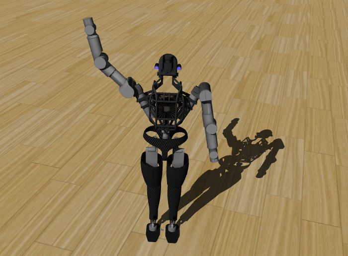
Instead of designing every behavior only around a laboratory demonstration, the team could measure progress against work that exists inside a factory.
That is how part sequencing became important.
The task looks simple from a distance.
Pick a specific automotive component from one container.
Carry it.
Place it into another rack or dolly in the required sequence.
But the robot has to perceive the correct part, navigate around fixtures, choose a grasp, maintain balance, move the object and complete the placement.
A commercial application turns many research capabilities into one repeatable workflow.
Part Sequencing Became the First Industrial Application
Boston Dynamics chose automotive part sequencing as Atlas’ first major industrial application.
In a mixed-model vehicle plant, parts arrive from suppliers in containers.
Those components need to be reorganized into the exact sequence required by the assembly line.
Atlas has been trained to move parts such as engine covers from supplier containers into sequencing dollies.
Boston Dynamics uses the task because it combines several capabilities in one workflow.
Vision identifies bins and fixtures.
Manipulation selects and grasps the component.
Whole-body control keeps the robot balanced while reaching and carrying.
Navigation moves the robot through the workspace.
State estimation tracks both the robot and the object.
The sequencing task therefore becomes a practical integration test.
One successful pick is useful.
A production workflow needs the complete loop to repeat across many parts and changing conditions.
That is the difference between demonstrating a behavior and building an industrial application.
The 2025 Hyundai Pilot Put Atlas Into a Customer Factory
Boston Dynamics moved the electric Atlas into Hyundai Motor Group Metaplant America in Georgia for field testing in 2025.
Hyundai describes the pilot as part of the robot’s path toward commercialization.
Atlas repeatedly performed sequencing tasks involving automotive parts and racks.
Boston Dynamics says the deployment helped the team test application readiness outside the lab.
That matters because a customer factory has its own geometry, fixtures, lighting, schedules and operating systems.
The robot has to work inside that environment rather than a workspace designed only for robotics research.
Field testing also produces a different kind of engineering feedback.
The team can see which parts of perception need refinement.
Which grasps appear repeatedly.
How the robot interacts with real containers.
How operators communicate work.
How maintenance fits around production.
The factory becomes part of the development process.
The Product Version Is Built Around Repeatable Manufacturing
A product robot also has to be manufacturable.
Boston Dynamics says the 2026 Atlas product version reduces the number of unique parts and uses components designed for compatibility with automotive supply chains.
That is a product-engineering decision.
Research hardware can evolve quickly between builds.
Production hardware needs a more controlled bill of materials.
Parts have to be sourced.
Assemblies need repeatable processes.
Quality checks need stable specifications.
Replacement components need to be available.
Hyundai Motor Group brings another layer through its manufacturing network.
Hyundai says it plans to use its mass-production capabilities to support the expansion of Atlas production and deployment.
The robot therefore sits inside a wider industrial system.
Boston Dynamics develops the humanoid.
Hyundai contributes manufacturing scale and customer environments.
The product architecture has to work across both.
Atlas Has 56 Degrees of Freedom and Continuous Joint Rotation
The product version of Atlas uses 56 degrees of freedom.
Boston Dynamics also describes its joint range as continuous.
That gives the robot movement options beyond directly copying human anatomy.
A humanoid shape helps Atlas work in spaces designed around people.
But the robot does not have to reproduce every human mechanical limitation.
The joints can rotate through ranges selected for industrial manipulation.
Boston Dynamics has shown Atlas turning its body while carrying objects and using orientations that let the robot approach a task from different directions.
This matters inside a factory.
A rack may be behind the robot.
A container may be low.
A part may require a different grasp angle.
The robot’s morphology gives the planner more ways to solve the same physical task.
The product specification therefore connects mechanical design directly to application flexibility.
The Product Hardware Is Sized Around Industrial Work
Boston Dynamics lists Atlas at 1.9 meters tall and 90 kilograms.
Its current specification gives an instantaneous payload capacity of 50 kilograms, a sustained capacity of 30 kilograms and a one-handed capacity of 20 kilograms.
Reach is listed at 2.3 meters.
Those numbers define the physical envelope of the robot.
They tell an application engineer what kinds of bins, shelves, parts and workstations can be considered.
The robot also includes tactile sensing in its fingers and palm together with a 360-degree camera view.
That connects physical manipulation with perception.
The hands interact with the object.
The vision system models the surrounding workspace.
The body provides the reach and payload.
An industrial platform needs all three layers to be specified because the task is defined by the complete mechanical system, not one actuator.
Autonomous Battery Swapping Turns Power Into a Workflow
Battery operation becomes part of deployment when a robot is expected to work across shifts.
Boston Dynamics lists four hours of typical battery life and two hours under heavy lifting.
Atlas can autonomously navigate to a charging station and replace its own battery.
The current specification lists an autonomous battery-swap time of about three minutes and a charge time of 1.5 hours.
That changes the power workflow.
An operator does not have to manually open the robot and replace a pack every time energy runs low.
Battery replacement becomes another autonomous task.
The robot can pause its assigned work, move to the station, exchange the battery and return.
That is a product feature rather than a locomotion feature.
It exists because industrial operation includes energy management, shift scheduling and fleet availability.
The robot has to manage its own supporting infrastructure as part of the work cycle.
Serviceability Becomes a First-Class Design Requirement
Commercial robots also need a maintenance model.
Boston Dynamics lists Atlas components as modular and field replaceable.
The company says limbs can be replaced in the field and plans customer self-repair certification paths.
That changes the way the hardware is designed.
A research robot can return to the engineering team for extensive work.
A deployed robot needs maintenance that fits the customer’s operating environment.
Components need defined replacement procedures.
Technicians need access.
System monitoring needs to identify what requires service.
Replacement parts need known interfaces.
Boston Dynamics also gives Atlas an IP67 rating and an operating-temperature range from minus 20 to 40 degrees Celsius.
Those specifications describe the environment the product is designed to operate within.
The product version is therefore defined not only by what it can do when everything is running.
It is also defined by how it is maintained between tasks.
Safety Systems Are Integrated Into the Product Architecture
Atlas is designed for workspaces where people may also be present.
Boston Dynamics lists human detection and fenceless guarding in its current product specification.
The company describes an onboard safety system that detects people and vehicles around the robot.
If a person enters a defined nearby area, the robot can pause and wait.
Padding and reduced pinch-point exposure are also part of the current product design.
These are product-level systems because deployment depends on the complete operating environment.
The autonomous behavior decides where the robot wants to move.
The safety layer monitors the surrounding workspace.
The factory defines the broader process around the robot.
That creates several levels of control working together.
The robot is not only a machine that can walk and manipulate.
It is a machine being designed to operate as part of an industrial workplace.
Orbit Connects Atlas to Enterprise Systems
A factory robot also needs software above the robot itself.
Boston Dynamics uses Orbit as its fleet and enterprise-management layer.
Orbit can connect robotics workflows to Manufacturing Execution Systems, Warehouse Management Systems and other systems of record.
That link is important.
A factory does not assign work only through a person standing next to the robot.
Orders already exist inside digital systems.
Inventory has identifiers.
Production has schedules.
Parts can be tracked through barcodes and RFID.
Boston Dynamics lists barcode scanning and RFID as Atlas workflow integrations.
Orbit provides the management layer around those operations.
It can assign work, monitor performance and connect the robot fleet to the wider enterprise process.
That turns Atlas from an isolated autonomous machine into one endpoint inside a software-defined factory workflow.
One Learned Skill Can Be Distributed Across a Fleet
Boston Dynamics also treats learned robot behavior as a fleet asset.
The company says that when one Atlas learns a new skill, that task can be deployed across the wider Atlas fleet.
That changes the economics of training.
The physical work happens locally.
The learned behavior can become reusable software.
A robot can be trained for a sequencing operation.
Once the behavior is validated, the same capability can be delivered to other compatible Atlas systems.
The exact deployment still depends on the application, environment and integration.
But the model of improvement is no longer one robot at a time.
The fleet can share behavior updates.
That makes Atlas closer to an enterprise software platform.
Hardware performs the task.
Software defines the learned capability.
Fleet management distributes and monitors it.
This is one of the clearest ways the product version moves beyond the identity of one humanoid robot.
Reinforcement Learning Is Moving From Research Into Product Skills
Atlas behavior development now uses reinforcement learning, teleoperation data and learned behavior models as part of the product pipeline.
Boston Dynamics and the Robotics & AI Institute formed a joint reinforcement-learning program in 2025 for the electric Atlas.
Boston Dynamics also describes using reinforcement learning in simulation and from teleoperated demonstrations for factory behaviors.
The company has applied these methods to walking, manipulation, carrying and full-body movement.
The important change is where those methods end up.
They are not only research outputs.
They feed skills intended for industrial applications.
A policy trained in simulation can become part of a sequencing behavior.
A teleoperated demonstration can provide data for manipulation.
A whole-body controller can support lifting.
The research pipeline becomes a production-skill pipeline.
That is another layer required for a humanoid platform that is expected to learn new physical tasks over time.
Google DeepMind Adds Foundation Models to the Atlas Roadmap
Boston Dynamics and Google DeepMind announced a new AI partnership at CES 2026.
The two teams plan to combine Gemini Robotics foundation models with the new Atlas fleet.
The stated focus is industrial work, beginning with manufacturing.
This adds another software layer to the product roadmap.
Boston Dynamics already has locomotion, whole-body control, manipulation, perception and application-specific policies.
Foundation models can add broader reasoning and generalization capabilities above those systems.
The partnership is research work, so the exact production behaviors will develop over time.
But the architecture is clear.
Atlas is not being designed around one fixed set of hard-coded tasks.
The robot platform is expected to receive new behaviors through learning systems and foundation models.
That gives the product a software roadmap alongside its hardware roadmap.
Hyundai Is Building a Training and Validation Pipeline Around Atlas
Hyundai is also building infrastructure around the robot.
Its Robotics Metaplant Application Center, or RMAC, opened in the United States in 2026.
Hyundai describes RMAC as a site for training manufacturing AI robots, collecting real-world data, testing and verification before production deployment.
The Group says Atlas robots trained there are planned to begin sequencing work at Hyundai Motor Group Metaplant America from 2028, with more complex manufacturing operations targeted later.
Those dates are Hyundai’s roadmap.
They show the structure behind the rollout.
Train.
Validate.
Deploy.
Collect operational data.
Retrain.
Expand the task set.
The robot is only one piece.
The training center, factory, software systems and fleet-management process form the wider industrial platform around it.
The 2026 Product Version Has Already Moved Into Public Deployment
Atlas also made a public appearance at the 2026 FIFA World Cup.
Hyundai used the product robot during a live Round of 16 match environment in July.
Atlas performed football-inspired movements and delivered the ceremonial match ball.
Boston Dynamics says the same reinforcement-learning and whole-body-control methods used for that public performance are related to how the team develops industrial robot behaviors.
The event itself is not a factory task.
What matters is the deployment process.
The robot had to operate outside the lab.
It had to execute a defined sequence in a live environment.
The team tested the behavior in real-world conditions before the event.
Boston Dynamics describes that approach as part of the transition from prototype demonstrations toward production systems that need repeatable behavior.
Public deployment becomes another validation environment for the product architecture.
Atlas Is Becoming an Industrial Platform, Not Just a Humanoid Robot
The change in Atlas becomes clearer when all of these layers are placed together.
The electric robot provides the body.
Fifty-six degrees of freedom provide movement.
Tactile sensing and 360-degree vision provide physical awareness.
Autonomous battery swapping manages energy.
Modular field-replaceable components create a service model.
Safety systems support shared workplaces.
Orbit connects the fleet to MES, WMS, barcode and RFID workflows.
Learned behaviors can move across multiple robots.
Reinforcement learning and behavior models create new physical skills.
Google DeepMind adds foundation-model research.
Hyundai provides customer factories, RMAC training infrastructure and a deployment roadmap.
Boston Dynamics is manufacturing the product version now.
That is a much larger system than one humanoid completing one task.
Atlas is becoming a hardware platform, software platform and fleet platform at the same time.
The research robot proved what the body could learn.
The industrial platform has to make those capabilities deployable, maintainable and repeatable.
That is the upgrade.
Robots Are Starting to Share a Planning Layer
Robotics is beginning to separate planning from physical execution more clearly.
One robot may have wheels.
Another may have two arms.
Another may be a humanoid.
Their bodies are different, but a higher-level model can still reason about the same shared task.
Google introduced Gemini Robotics ER 2 on July 30, 2026 as an embodied-reasoning model for robotics.
Its job is not to directly generate every motor command.
It sits above lower-level control systems.
The model can watch the physical environment, understand what is happening, plan a multi-step task, decide which tool or robot capability should be used next and then hand the motor execution to a Vision-Language-Action model or another robotics API.
ER 2 also adds multi-robot coordination.
That gives one reasoning layer a way to work across different machines in the same environment.
The important change is architectural.
A robot fleet no longer has to be understood only as several independent machines.
It can also be treated as a collection of physical capabilities coordinated by one shared reasoning system.
Gemini Robotics ER 2 Is the High-Level Brain, Not the Motor Controller
Google describes Gemini Robotics ER 2 as a high-level brain for robots.
That wording defines its place in the stack.
The model receives text, images, video and audio.
It reasons about the physical environment.
It can choose tools.
It can plan a sequence.
But the lower-level movement can remain inside another system.
A VLA model can translate vision and language into motor action.
A navigation API can move a mobile robot.
A manipulator API can control an arm.
A grasping system can handle the final contact with an object.
ER 2 coordinates those capabilities instead of replacing every controller underneath them.
This creates a hierarchy.
The user states the goal.
ER 2 decides what the goal requires.
The robot APIs or VLA models execute the physical operations.
That separation also lets the same reasoning architecture work with different robot bodies.
The model can call whatever lower-level interface the developer exposes as a tool.
Robot Capabilities Become Tools the Model Can Orchestrate
Gemini Robotics ER 2 uses a tool-oriented architecture.
Developers can expose low-level robot controls as callable functions.
A navigation function can move to a location.
A camera function can inspect the scene.
A manipulator function can position an arm.
A VLA model can perform a learned physical behavior.
The reasoning model does not need every physical detail encoded inside one prompt.
It can select from the available tools as the task progresses.
Google’s developer documentation calls this task orchestration.
The model combines spatial reasoning with custom robotics APIs to complete longer sequences.
That makes robot control look increasingly like software-agent orchestration.
The difference is the output.
A software tool may edit a file.
A robotics tool may move a machine.
The planning structure is similar: understand the current state, choose the next capability, receive the result and continue.
Continuous Video Gives the Planner a Live View of Progress
ER 2 adds a stronger temporal layer through continuous video.
A physical task unfolds over time.
The robot moves.
An object changes position.
A container becomes full.
A tool reaches the intended location.
The reasoning system needs to know when one step is actually complete before it moves to the next.
Google says ER 2 can watch continuous video feeds to track progress and verify task completion.
That gives the planner a live source of state rather than only a sequence of isolated images.
The model can observe what the robot is currently doing while it is already reasoning about the following step.
This changes the rhythm of the control loop.
Perception and planning can overlap.
The robot does not always have to stop completely before the reasoning layer begins the next decision.
The model can keep watching the task as it unfolds.
Moment Finding Helps the Model Decide When a Step Is Complete
One of the new evaluation areas is moment finding.
The model receives a video and has to identify the moment when a defined event occurs.
In robotics, that can mean the moment a subtask has been completed.
Google gives examples such as tightening a light bulb or tying a trash bag.
ER 2 can use the continuous video to decide when the required state has been reached.
Google reports 91.3 percent accuracy on its moment-finding evaluation with a mean absolute distance of 0.96 seconds.
Google also reports that the model executes this evaluation four times faster than the larger comparison category used in its release.
Those are Google’s published benchmark results for its test setup.
The important architectural point is that timing becomes part of embodied reasoning.
The model is not only asking what is in the scene.
It is asking when the scene has reached the state required for the next action.
Planning Can Continue While the Robot Is Already Acting
Google designed the ER 2 control loop so reasoning and action can overlap.
The model can think about the next step while the current physical action is still being performed.
This matters because robotics operates in real time.
A long pause between every decision can change the feel of a multi-step workflow.
ER 2’s streaming version integrates with the Gemini Live API through a bidirectional streaming endpoint designed for latency-sensitive robotics work.
The streaming endpoint can receive continuous audio and video while using function calling to control robot tools.
That gives the planning system a persistent connection to the physical process.
The robot acts.
Video continues arriving.
The model updates its understanding.
The next tool call can be prepared from the current state.
This is closer to an ongoing control conversation than a sequence of isolated prompt-response requests.
Google Provides Two ER 2 Endpoints for Different Control Loops
Gemini Robotics ER 2 currently has two model endpoints.
The standard preview endpoint is gemini-robotics-er-2-preview.
It supports multimodal input, function calling, structured outputs, code execution, search grounding and other Gemini capabilities.
The streaming endpoint is gemini-robotics-er-2-streaming-preview.
It is optimized for the Live API and low-latency robotics workflows.
Both accept text, images, video and audio as input.
Both produce text output that can include reasoning results and tool calls interpreted by the application.
Google documents an input context window of 131,072 tokens and an output limit of 65,536 tokens for the current preview endpoints.
The two-endpoint structure gives developers a choice.
A task that does not require continuous low-latency control can use the standard model.
A robot that needs ongoing video and audio interaction can use the streaming path.
Multi-Robot Collaboration Adds Another Level Above One Machine
The largest conceptual change in ER 2 is multi-robot collaboration.
Google demonstrates different robot bodies working on one shared task.
The reasoning layer can understand that the machines have different physical capabilities.
It can then coordinate a handoff between them.
Google’s release shows Apptronik’s Apollo 2 working with a Franka FR3 Duo system.
The two robots do not need identical bodies.
One can be better positioned for one part of the workflow.
Another can handle the next part.
ER 2 provides the shared semantic plan between them.
This turns robot diversity into something the planner can reason about.
The fleet does not need to behave as several copies of one machine.
Different forms can contribute different capabilities to the same objective.
A Shared Semantic Plan Lets Different Robot Bodies Work Together
Multi-robot work requires more than sending the same command twice.
Different machines may represent movement differently.
One may navigate through a room.
Another may stay fixed at a workstation.
One may have a humanoid arm configuration.
Another may use a dual-arm manipulator.
The high-level instruction therefore has to be translated into body-specific execution.
ER 2 handles the shared semantic layer.
The model understands the task in terms of objects, goals, sequence and physical relationships.
Each robot’s lower-level controller handles the mechanics of its own body.
That separation allows the planner to say what should happen without requiring the same motor representation across every machine.
The result resembles a team structure.
The shared plan defines the mission.
Each robot contributes the physical actions its own hardware is designed to perform.
Apollo 2 Shows How a Humanoid Can Become One Capability in the Team
Apptronik’s Apollo 2 is one of the robot platforms shown in Google’s multi-robot work.
Apollo 2 is a modular humanoid platform available with bipedal and wheeled-base configurations.
Apptronik describes it as a physical platform designed for embodied AI, with perception, manipulation and mobility systems that can work with higher-level models.
Apptronik and Google DeepMind already have a research partnership around Gemini Robotics.
Apptronik’s Robot Park also collects real-world task data from Apollo 2 fleets for the development of future robotics models.
Inside a multi-robot plan, the humanoid does not need to become the entire system.
It can be one physical participant.
The reasoning model can assign the part of the task that fits Apollo’s body and then coordinate another machine for a different step.
Franka's Dual-Arm Platform Adds a Different Physical Skill Set
The Franka FR3 Duo represents another kind of robot.
It uses two collaborative robotic arms rather than a humanoid body.
Franka has demonstrated Gemini Robotics with its dual-arm systems for real-time planning and multi-step manipulation.
This gives the shared planner another physical form to work with.
A dual-arm station can specialize in coordinated manipulation around a fixed workspace.
A mobile or humanoid platform can approach the task from another position.
The high-level model can reason about the complete workflow while the local robot controller handles the detailed motion of each arm.
That is the advantage of separating embodied reasoning from body-specific execution.
The reasoning model can remain common.
The machines underneath can stay specialized.
Spot Shows the Same Planning Pattern Through Robot APIs
Boston Dynamics Spot demonstrates the same architecture from another direction.
Google used ER 2 to orchestrate Spot APIs for navigation and manipulator movement.
The user can give a natural-language task.
ER 2 can decide which Spot capabilities need to be called and in what order.
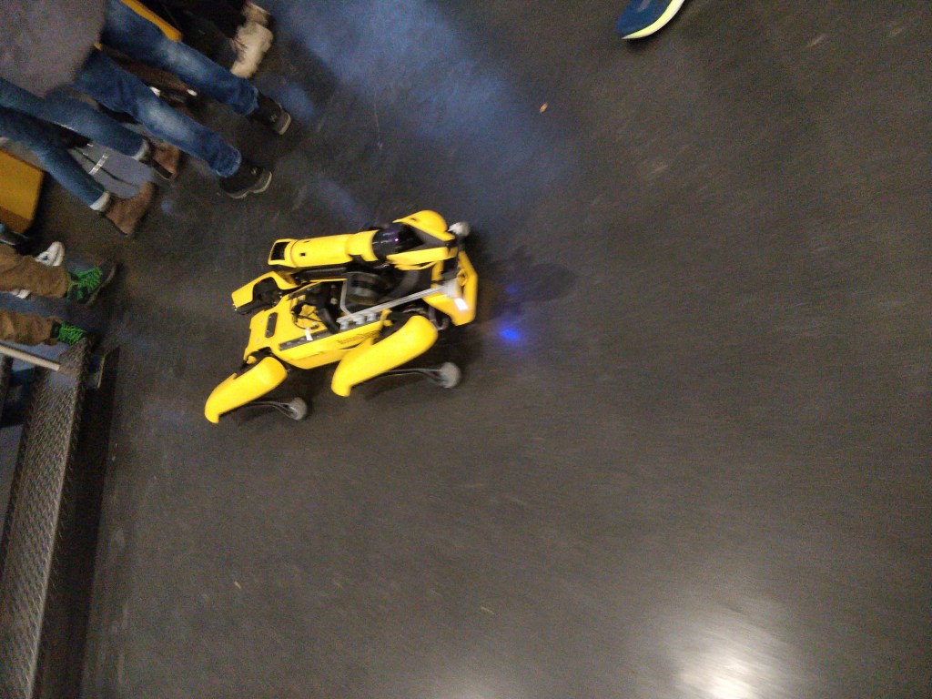
Boston Dynamics has also documented earlier work connecting Gemini Robotics to Spot through a tool layer built on the Spot SDK.
The reasoning model acted like a high-level operator.
Spot’s existing autonomy, navigation and manipulation systems remained underneath it.
ER 2 extends that orchestration model with real-time streaming and stronger progress understanding.
The important part is that the robot API becomes a tool interface.
A mature robot platform does not have to discard its own control stack.
The higher-level model can coordinate the capabilities that already exist.
Spatial Reasoning Connects Language to Physical Coordinates
Planning in the physical world also requires spatial grounding.
Google’s robotics API documentation exposes capabilities for pointing to objects, tracking them in video, detecting bounding boxes and planning trajectories.
A model can receive an image and return normalized coordinates for visible objects.
Those coordinates can then be passed to another robotics system.
This creates a bridge between language and geometry.
The user says which object matters.
The model identifies it.
A robot controller receives the spatial output.
The physical system acts on that location.
Spatial reasoning becomes another shared service in the planning layer.
It is not tied to one manipulator.
Any compatible lower-level system can use the structured location information the model produces.
Tool Calls Can Reach Software Services as Well as Robot Hardware
ER 2 can also call non-robot tools.
Google says the model can use services such as Google Search or user-defined functions.
That widens the planning loop.
A robot task may require information that is not visible in the room.
The model can retrieve the information.
Then it can continue the physical workflow.
The same agent can therefore move between digital and physical tools.
Search can answer a question.
A database can provide a parameter.
A robot API can move a machine.
A VLA model can execute manipulation.
ER 2 coordinates the sequence.
This is another reason embodied reasoning is becoming part of the broader agent architecture.
The distinction between software tools and physical tools remains important at the execution layer.
At the planning layer, both can appear as capabilities available to the same task.
ER 2 Is Available to Developers as a Preview
Gemini Robotics ER 2 is currently distributed as a preview model.
Google makes the standard endpoint available through the Gemini API and Google AI Studio.
Google also lists Gemini Enterprise Agent Platform as a private-preview distribution path.
The model card identifies ER 2 as a Vision-Language Model based on Gemini 3.5 Flash.
Google says it was trained on Gemini 3.5 data together with additional embodied-reasoning datasets.
The current release is therefore a developer platform as well as a research result.
Developers can connect their own robot APIs.
They can stream multimodal input.
They can test spatial reasoning, progress understanding and task orchestration.
The preview status is important because it defines where the technology sits today.
The architecture is accessible.
The ecosystem is still actively developing around it.
Robots Are Starting to Plan Together, Not Just Act Alone
Gemini Robotics ER 2 shows a different direction for robotics.
The intelligence layer does not have to live entirely inside one robot body.
A high-level model can watch the environment.
Understand the shared task.
Plan several steps.
Track progress through continuous video.
Decide when one step is complete.
Call robot APIs or VLA models.
Coordinate different machines.
Keep reasoning while physical actions continue.
Apollo 2, Franka’s dual-arm platform and Spot illustrate three different robot forms that can participate in this kind of architecture.
The bodies stay different.
Their lower-level controllers stay different.
The planning layer provides a common semantic structure above them.
That is the important shift.
The future robot team may not be a fleet of identical machines running the same behavior.
It can be a collection of specialized bodies coordinated by a shared reasoning system.
The robot stops being the only unit of intelligence.
The workflow becomes the unit.
That is the upgrade.